- Model Overview
- Component /Feature Overview
- Installation
- Operation
- Functions & Controls
- 20-Litre Controls
- 20-Litre - Initial Cold Water Operation
- 30-Litre Controls
- 30-Litre - Initial Cold Water Operation
- 30-Litre - Temperature Control
- 60-Litre Controls
- 60-Litre - Initial Cold Water Operation
- 20/30-Litre - CO2 Bottle Installation
- 30/60-Litre - Refillable CO2 Bottle Installation
- Maintenance & Cleaning
- Advanced Troubleshooting
- Exploded Diagrams
- Tap Exploded Diagram
- 20-Litre - Chilled & Ambient Exploded Diagram
- 20-Litre - Chilled, Ambient & Sparkling Exploded Diagram
- 30-Litre - Chilled, Ambient & Sparkling Exploded Diagram
- 60-Litre - Chilled, Ambient & Sparkling Exploded Diagram
- Tap Parts List
- 20-Litre - Parts List
- 30-Litre - Parts List
- 60-Litre - Parts List
- Technical Information
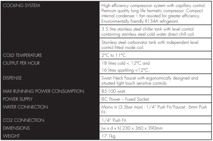
- Specification (20Litre)
- 20-Litre - Chilled & Ambient Electrical Circuit Diagram
- 20-Litre - Chilled, Ambient & Sparkling Electrical Circuit Diagram
- 20-Litre - Chilled & Ambient Water Pathway Diagram
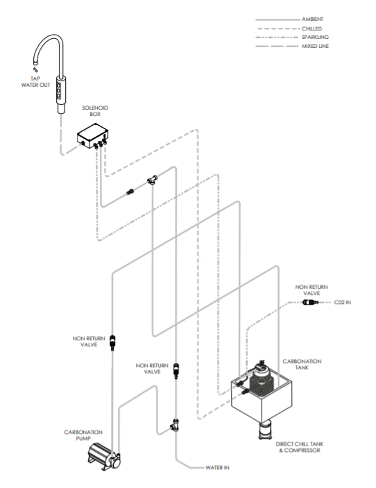
- 20-Litre - Chilled, Ambient & Sparkling Water Pathway Diagram
- 30-Litre - Technical Information
- 30-Litre - Electrical Circuit Diagram
- 30-Litre - Water Pathway Diagram
- 60-Litre - Technical Information
- 60-Litre - Electrical Circuit Diagram
- 60-Litre - Water Pathway Diagram
Release date 21.06.2018
U1.S1 (20L, 30L, 60L) – Install & Operation Manual
Model Overview
Introduction
The u1 epitomises cutting-edge design and innovation with its contoured tap and compact under-counter unit. This is our most discreet range and will fit into
any environment seamlessly.
The under-counter dispensers supplied
with this tap are manufactured with the most modern and innovative technologies. All the materials and
components are tested during the entire production process in order to satisfy all expectations.
20-Litre:
Alongside a robust steel frame this dispenser features stylish, injection moulded front side and top panels.
| COOLING SYSTEM | High efficiency compression system with capillary control. Environmentally friendly R600 refrigerant. |
| COLD TEMPERATURE | 2°C to 11°C. |
| OUTPUT PER HOUR | 18 litres cold < 12°C and 16 litres sparkling <12°C. |
| DISPENSE | Swan Neck Faucet with ergonomically designed and situated light touch sensitive controls. |
| MAXIMUM RUNNING POWER CONSUMPTION | 85-100 watt. |
| POWER SUPPLY | IEC Power – Fused Socket. |
| WATER CONNECTION | Mains in (3.5bar max) - 1/4” Push Fit/Faucet - 6mm Push Fit. |
| C02 CONNECTION | 1/4” Push Fit. |
| DIMENSIONS | (w x d x h) 230 x 360 x 390mm. |
| WEIGHT | 17.1Kg. |
| CUPBOARD VENTILATION | Recommended |
30-Litre:
With its low noise characteristics this unit can be installed in any environment where limited space is an issue. It is controlled by microprocessor which, via specially fitted sensors, will notify the user of any malfunctions and automatically turn off the dispenser when dangerous conditions arise. A separate monitoring system will also let the operator know when the water filter needs to be replaced.
| COOLING SYSTEM | High efficiency compression system with capillary control. Environmentally friendly R600 refrigerant. |
| COLD TEMPERATURE | 4°C to 8°C. |
| OUTPUT PER HOUR | 30 litres cold & sparkling. |
| DISPENSE | Swan Neck Faucet with ergonomically designed and situated light touch sensitive controls. |
| MAXIMUM RUNNING POWER CONSUMPTION | 150 watt. |
| POWER SUPPLY | IEC Power – Fused Socket. |
| WATER CONNECTION | Mains in (5bar max) - 3/4” Female BSP. |
| C02 CONNECTION | 1/4” Quick Fitting. |
| DIMENSIONS | (w x d x h) 245 x 365 x 375mm. |
| WEIGHT | 16Kg. |
| CUPBOARD VENTILATION | Recommended |
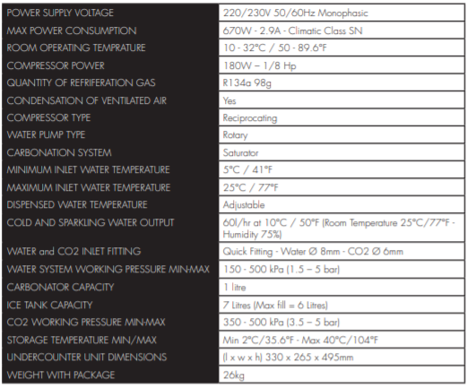
60-Litre:
Using “Ice Bank” technology this unit can dispense up to 60 litres of water per hour, completely satisfying the demand of small, medium and large restaurants and catering areas with high performance and a compact design.
| COOLING SYSTEM | High efficiency compression system with capillary control. Environmentally friendly R600 refrigerant. |
| COLD TEMPERATURE | 2°C to 11°C. |
| OUTPUT PER HOUR | 60 litres cold & sparkling at 10°C. |
| DISPENSE | Swan Neck Faucet with ergonomically designed and situated light touch sensitive controls. |
| MAXIMUM RUNNING POWER CONSUMPTION | 360 watt. |
| POWER SUPPLY | IEC Power – Fused Socket. |
| WATER CONNECTION | Mains in (5bar max) - 8mm Quik Fitting. |
| C02 CONNECTION | 6mm Quick Fitting. |
| DIMENSIONS | (l x w x h) 269 x 467 x 510mm. |
| WEIGHT | 26Kg. |
| CUPBOARD VENTILATION | Recommended |
Component /Feature Overview
U1 Tap - Major Components

Please Note: Mains Installation Kit & Filters are supplied as extra items according to individual ordering requirement.
20-Litre - Major Components

30-Litre - Major Components

60-Litre - Major Components

Installation
Tap Installation


When planning and providing for the connection to the
services, always allow for easily accessible service isolator fittings and for the position of an external water filter.

Identify a suitable position for the swan neck faucet. A 33-35mm (max) hole is required.

When positioning to drain over an existing sink bowl, allow for the reach of the swan neck or otherwise the position of any optional drip tray.

Also allow for the height of the swan neck under any
overhanging cupboard/shelf.

Allow for the space needed for forming the required hole. Relate the selected position to the underneath of the counter and check for any obstructions.

Allow sufficient space for fitting a back nut to the faucet stem.

Carefully form the needed hole using the correct type of cutter for the work surface material.
Observe all local occupational health and safety requirements.

Remove the back nut and washer from the faucet and carefully feed the connecting pipe tail and ribbon cable through the hole formed in the work surface. Ensure the sealing O ring is prefitted in the base of the faucet. You may want to apply a thin bead of silicone sealant also.

With the faucet control panel in the right position, carefully refit the back washer and nut. Take care not to over-tighten.

Fit optional Drip Tray at this stage (if selected).

Connect the Tap control panel membrane to the Faucet
connection harness.

If applicable. Connect the Faucet connection harness to the harness connection Port.
20-Litre - Undercounter Unit Installation & Water Connection

Check the main components are present as per the Major Components Contents Diagrams

Position the unit in place, ensuring it is level and stable.

Connect to the water supply.

The maximum recommended inlet pressure is 3.5bar. We recommend fitting a check valve, a pressure reducing valve and a ‘Waterblock’ device. (These are available as part of our optional Installation Kit). When fitting a Waterblock device we recommend a minimum setting of ‘2’ be used.

Pre-flush and fit the filter in an accessible position.

Always allow adequate connecting pipe length
to enable the unit to be sufficiently moved for any future disconnection.

Connect the faucet connection harness to the unit.

Turn on the water supply and check for any leaks.

Connect the IEC power cordset to the electricity supply,
and switch on power.

The Direct Chill system should now be heard to begin filling. This may continue for a few minutes depending upon water pressure. (NB: Any immediate whining noise from the DC pump should soon stop as the water level in the system rises).

Upon completing the installation process, proceed
to flush out the dispense water lines using the buttons on the tap. We recommend that a minimum of 10lts is flushed through the unit. (Chilled approx.8lts and Ambient approx. 2lts).

Allow up to 1hr for the initial cooling cycle to complete.
30-Litre - Undercounter Installation & Water Connection
NOTE:
- Any temporary water connections are detrimental to the correct functioning of this dispenser.
- During installation only new water supply pipes must be used. The water supply line for this dispenser must consist of an interception valve (tap) and non-return valve.
- For the correct and safe functioning of this dispenser, the water mains must satisfy the criteria detailed in the specification section of this manual (see Specification 30-Litre)
- If mains water is greater than 3.5 bar, a pressure reducing valve (PRV) needs to be fitted to bring the pressure down to 3bar.

- Fittings and pipes for connection to the water mains must be food certified. Optional accessories such as filters and pre-filters, to be assembled on the water mains after the interception valve, must also be certified for food compatibility.
- Check the main components are present as per the list in the Major Components Diagram
- Pre-flush and fit the filter in an accessible position.
- Position the unit in place, ensuring it is level and stable.
- Connect the water supply pipe to the fitting supplied in the install kit.
- Once connected to the mains, position a suitable container at the open end of the supply pipe and turn on the water to drain and clean the tube; clear the external filter and other outer accessories (if attached) by draining at least 2 litres of water. After this operation turn off the tap.
- Screw the 3/4” female BSP on to the threaded coupling used to connect the water supply pipe to the dispenser. Remember to insert the supplied gasket.
- Connect the open end of the tube to the 3/4” female BSP located on the dispenser (see Fig1).
- Turn on the tap making sure there are no leaks along the supply line (see Fig2).
- Always allow adequate connecting pipe length to enable the unit to be sufficiently moved for any future disconnection.

Fig 1

Fig 2
60-Litre - Undercounter Unit Installation & Water Connection
NOTE:
- Any temporary water connections are detrimental to the correct functioning of this dispenser.
- During installation only new water supply pipes must be used. The water supply line for this dispenser must consist of an interception valve (tap) and non-return
valve. - For the correct and safe functioning of this dispenser, the water mains must satisfy the criteria detailed in the specification section of this manual (see Specification 60-Litre).
- If the pressure of the water mains is greater than 3.5 bar, it will be necessary to install a pressure reducer after the interception valve, setting the pressure to 3 bar. Pressure peaks greater than 6.5 bar may cause the safety valve to open.
- Fittings and pipes for connection to the water mains must be food certified.
Optional accessories such as filters andpre-filters, to be assembled on the water mains after the interception valve, must also be certified for food compatibility.
- Check the main components are present as per the lists on the Major Components Diagrams
- Pre-flush and fit the filter in an accessible position.
- Position the unit in place, ensuring it is level and stable.
- Screw the non-return valve on to the shut off valve along with the pressure reducer if necessary.
- Use the 1/2” or 3/4” fitting to connect the water supply pipe provided with the install kit to the mains.
- Connect the water supply pipe to the water supply fitting.
- Once connected to the mains, position a suitable container at the open end of the supply pipe and open the shut off valve to drain and clean the tube; clear the external filter and other outer accessories (if attached) by draining at least 5 litres of water. After this operation close the shut off valve.
- Connect the free end of the pipe to the water inlet point on the dispenser (see Fig1).
- Open the shut off valve making sure there are no leaks along the supply line (see Fig 2).
- Remove the lid and fill the ice bath up to the fill markers. Once full ensure the lid is replaced (see Fig 3).
- Always allow adequate connecting pipe length to enable the unit to be sufficiently moved for any future disconnection.

Fig 1

Fig 2

Fig 3
Installing the Solenoid Box
- Mount the Solenoid Box on the underside of the work top that the u1 tap is fixed to using screws provided (Try and keep as close as possible to the u1 Tap).
- Connect all outlet dispense options from unit to corresponding inlets on the solenoid box.
- Connect u1 tap pipe work to outlet of solenoid box.
Note: Please make sure electrical power is turned off: Connect power to inlet of transformer that is fixed at rear of unit. Connect lead from outlet of transformer to solenoid box.
4. Connect u1 membrane to solenoid box.
5. Turn on power supply and set up is now complete.
30/60-Litre - Ventilation Grill Installation
When Borg & Overström u1 undercounter units are installed inside a cabinet or housing, adequate ventilation is recommended to ensure that they operate satisfactorily.
During a cooling cycle it is normal for the unit to produce heat and the purpose of the ventilation is to provide a supply of air that can absorb the generated heat which otherwise will accumulate inside the cabinet or housing and reduce the cooling performance of the unit. The amount of heat generated by the cooling cycle depends directly upon the amount of usage – the
higher the usage, the more heat produced.
To provide adequate ventilation we recommend that air grilles/vents are fitted as supplied (or vent apertures formed) in the cabinet to allow an airflow as shown below. Normally this should be enough for all situations.
The air grilles fitted (or vent apertures formed) should each have a ventilation area equal to or greater than 25000mm2 and the air circulation path inside the cabinet/housing must be unobstructed. (eg: a vent grille with an overall size of 250mm x 100mm).
It is recommended that an inlet vent grille is set into the plinth with a corresponding vent grille in the base of the cabinet behind the undercounter unit to allow the air to flow past the condenser. An exhaust vent grille is
also required at the top if the cabinet. It is recommended either behind the tap in the work surface or at the side of the cabinet for a more unobtrusive appearance should this area be available.

Option 1 – Side View (Recommended air flow path from plinth to worktop).

Option 1 – Front View (Recommended air flow path from plinth to worktop).

Option 2 – Side View (Air flow from door or kick panel to worktop).

Option 3 – Front View (Air flow from side of cabient to worktop or opposite side panel).
General Safety

Operation
Functions & Controls

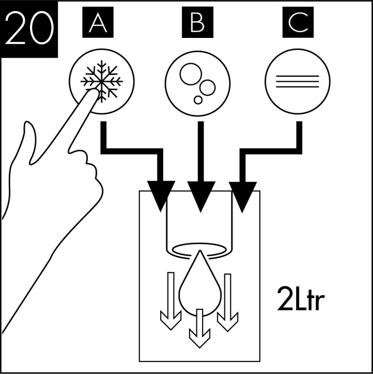
20-Litre Controls

20-Litre - Initial Cold Water Operation

Turn on the water supply and check for any leaks.

Connect the IEC power cord-set to the electricity supply, and switch on power.

The Direct Chill system should now be heard to begin filling. This may continue for a few minutes depending upon water pressure. (NB: Any immediate whining noise from the DC pump should soon stop as the water level in the system rises).

Upon completing the installation process, proceed to flush out the dispense water lines using the buttons on the tap. We recommend that a minimum of 10lts is flushed through the unit. (Cold approx.8lts and Ambient approx. 2lts).

Allow up to 1hr for the initial cooling cycle to complete.
NOTE:
If model includes the sparkling dispense option please refer to CO2 Bottle Installation
Cold Thermostat

30-Litre Controls

30-Litre - Initial Cold Water Operation
After carrying out the installation procedures detailed in the previous chapter, run the initial cold water operation as follows:
1. Ensure the CO2 bottle is properly connected to the dispenser (see Refillable C02 Bottle Installation).
2. Place a container with a capacity of 5 litres under the tap.
3. Dispense at least 3 litres of both ambient
and chilled water.
4. Hold the sparkling water button until sparkling water is dispensed.
30-Litre - Temperature Control
The cold water temperature control has 3 settings – 4c, 6c and 8c. The undercounter unit is factory set to 6c.
If any adjustment is required, please carry out the following steps:
1. Locate the button on the back top left of the unit (see Fig1).
2. Press and hold the button for approximately 3 seconds until you hear the signal beep, continue to hold whilst counting the number of bleeps. Use table below to set the temperature:
| 1 bleep | 4°C |
| 2 bleeps | 6°C |
| 3 bleeps | 8°C |
3. To change the setting: After carrying out steps 1 & 2, continue to hold the button on the back –
3a. To decrease the temperature,press the ambient dispense button 1x to reduce one stage or 2x to reduce two stages.

3b. To increase the temperature, press the cold dispense button 1x to raise one stage or 2x to raise two stages.
4. Release the programming button to save the selected setting.
5. Press and hold the programming button again and count the number of bleeps to confirm the setting is saved.

Fig 1

Fig 2
60-Litre Controls

60-Litre - Initial Cold Water Operation
After carrying out the installation procedures detailed in the previous chapter, run the initial cold water operation as follows:
1. Lift the upper plastic cover off of the dispenser by pulling it up.
2. If not done already, fill the ice tank with clean water paying special attention not to wet any of the electrical components.
3. Fill the ice tank to the arrow that indicates the maximum level (see Fig 1). After filling the tank do not move the dispenser as doing so could cause water to spill from the tank. NOTE: if this device is operated without water in the ice tank it will cause
serious damage to the machine.
4. Dry any drops or splashes caused by filling the ice tank.
5. Pull the ring of the safety valve on the carbonator, releasing gas for at least 2/3 seconds (see Fig 2).
6. Open the water shut off valve on the supply line.
7. Place a container with a capacity of at least 5 litres under the dispensing taps.
8. Dispense at least 3/4 litre of ambient still water, and at least 3/4 litre of chilled water.
9. Position the thermostat switch to number 7, and wait for 2 – 3 minutes.
10.Position the 5 litre container under the sparkling water tap and dispense until only gas comes out.
11.Replace the upper plastic cover and wait for 90 – 120 minutes before dispensing water again so ice may form in the tank.
12.Once started the device must be left operating permanently. If the power supply is interrupted for more than 2 – 3 hours it could cause faults within the ice tank and consequently freeze the water coil. NOTE: If a similar anomaly occurs follow ice bank
defrosting procedure (see Ice Tank Defrosting & Emptying – 60-Litre).

Fig 1

Fig 2

Turn clockwise to decrease water temperature
20/30-Litre - CO2 Bottle Installation

Unpack CO2 Regulator and fit elbow fitting to spigot outlet.

Attach the regulator to the disposable CO2 bottle, ensuring the small pressure relief vent in the stem is facing away from you or anyone else. Ensure the regulator is closed. Hand tighten securely.

Connect the assembled CO2 bottle and regulator to the CO2 inlet on the back (20L) or side (30L) panel using a ¼” pipe.

Stand the cylinder in a suitable place.

On the 20Litre variant: Do not open the regulator valve until the carbonated switch has been turned on.

After completing the water installation, turn on the soda power switch and the pump will run. Allow the carbonation tank to fill. (The carbonation pump will run for between 15 seconds – 2 minutes).). We recommend
between 3.5 – 5 bar (max). Do not exceed 5 bar pressure.

Flush through approximately 10 litres of water using the sparkling button. Depending on the inlet water pressure, on the 20Litre model you may have to pause approx. every 500ml to allow the carbonation tank to refill. Check and adjust the CO2 pressure accordingly.

It will be necessary to leave the machine for up to 1 hour for sparkling water to develop, by absorbing the CO2.
30/60-Litre - Refillable CO2 Bottle Installation
NOTE:
- Before connecting the CO2 bottle ensure the gas being used is food certified.
- Do not lay the CO2 bottle on its side whilst attaching the pressure reducer, make sure it is always in an upright position when carrying out this task.
- Always ensure the reducer’s working pressure is higher than the cylinders max pressure.
- Do not place hands or any other part of the body near the gas as this may cause freeze burns.
- A small amount of gas leakage during set up/replacement is normal.
- Connect the assembled CO2 bottle and regulator to the CO2 inlet on the rear panel (60L) using a 6mm pipe or side panel (30L) using a ¼” pipe (see Fig1)
- In instances where a refillable CO2 bottle is being used screw the pressure reducer on to the gas bottle with a spanner (28mm). If however a singleuse gas bottle is in operation, screw the reducer on to the bottle by hand.
- If using a refillable gas bottle open it by turning the upper hand grip counterclockwise (item1- fig 2).
- Ensure the CO2 bottle is securely connected to the dispenser using the 1/4” plastic tube.
- Insert one end of the tube into the quick fit coupling at the rear or side of the machine, and the other connected to the reducer of the gas bottle.
- Open the gas bottle by turning the upper hand grip counter-clockwise (item1- fig 2).
- Turn the black handle of the pressure reducer clockwise (turning towards the + sign) (item 2- fig 2).
- Check that any connection points are free of leaks using soapy water.
Adjusting Sparkling Water
By adjusting the pressure reducer it is possible to increase or decrease the amount the amount of CO2 present in the water; the optimal recommended values range from 2 – 5 bar. A higher pressure will increase the amount of carbonation in the water, with a lower pressure producing ‘slightly sparkling’ water. CO2 pressure must be set at +0.5Bar> incoming water pressure.
Replacing a Refillable CO2 Tank
- Detach the CO2 bottle from any supporting chains or belts.
- Close the valve at the top of the bottle by turning it clockwise until completely locked (item1- fig 2).
- Close the pressure reducer by turning the knob anticlockwise (item2- fig 2).
- Remove the CO2 pipe from the pressure reducer, and detach the other end from the dispenser.
- Screw the adapter (optional) for the external CO2 bottle to the new pressure reducer and tighten it firmly.
- Connect one end of the new CO2 pipe to the pressure reducer and the other to the appropriate connection point on the dispenser (see 30/60 Litre Major Components).
- Screw the ring nut of the adapter assembled on the pressure reducer to the CO2 bottle.
- Open the valve at the top of the new CO2 bottle.
- Reattach any chains or belts removed from the bottle and return it to its normal position.
- Check for leaks using soapy water.

Fig 1

Fig 2
Maintenance & Cleaning
Sanitisation Guide
The product is supplied from the factory in clean condition, but we recommend that a sanitisation procedure is caried out at the point of installation, according to the sanitisation instruction relevant to this model, which can be found in the respective Instruction & Operation Manual
NOTE: Failure to use sanitising products and processes approved by Borg & Overström will invalidate your warranty.
This operation must only be carried out by trained staff.
A sanitisation procedure is recommended every 6 months.
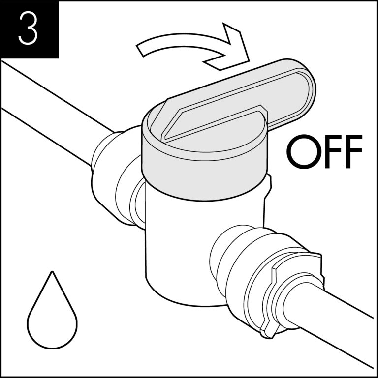
Turn off incoming mains water
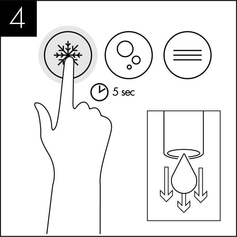
Briefly press chilled dispense button to release internal water pressure from the machine.
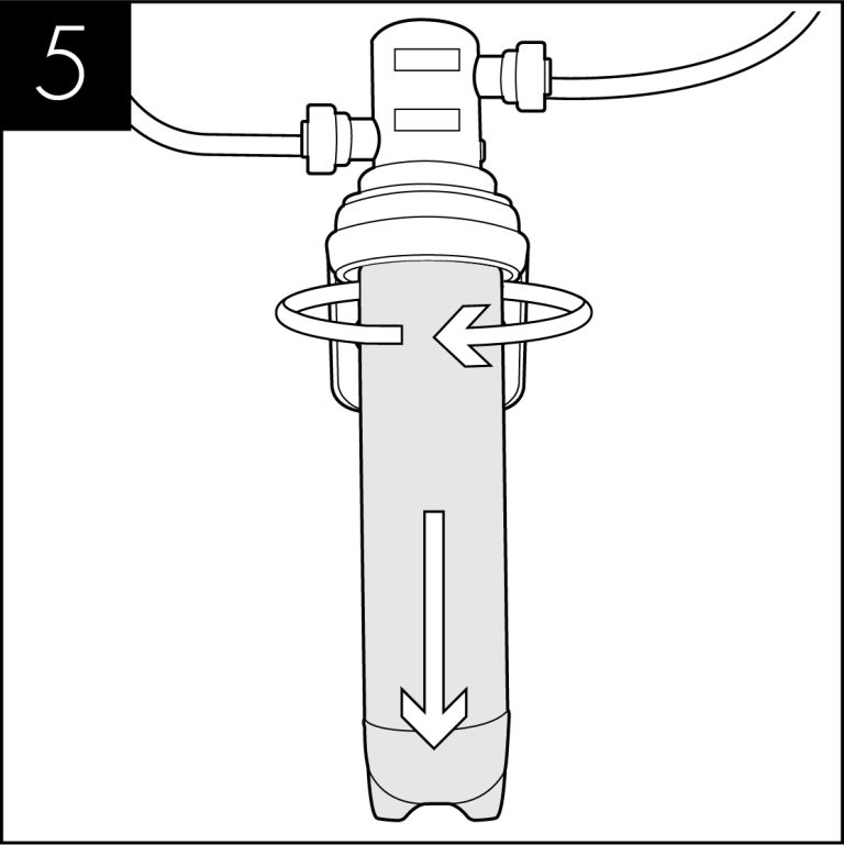
Remove the existing filter
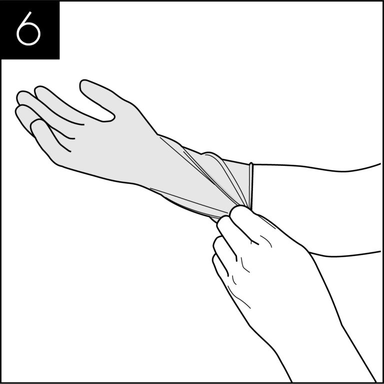
Use hand gel and put on protective gloves.
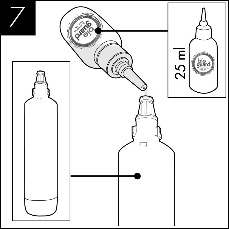
Add 25 ml of Bioguard Internal Sanitising Solution to a clean and empty service filter cartridge.
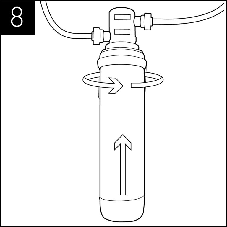
Connect to filter head.
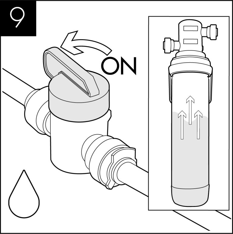
Turn on incoming water, allow the service filter cartridge to fill
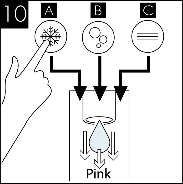
Dispense water using the chilled button until the water appears pink. Repeat with sparkling & ambient water buttons.
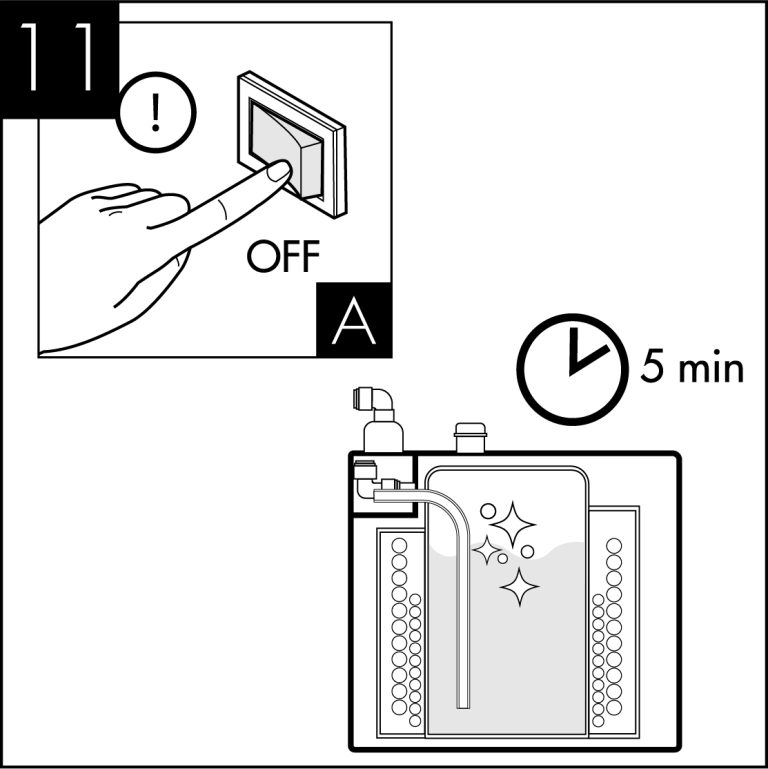
Leave the solution inside machine for sanitisation to take effect (minimum 5 minutes) while thoroughly cleaning the dispenser externally. (All maintenance operations must be carried out with the dispenser switched off.)
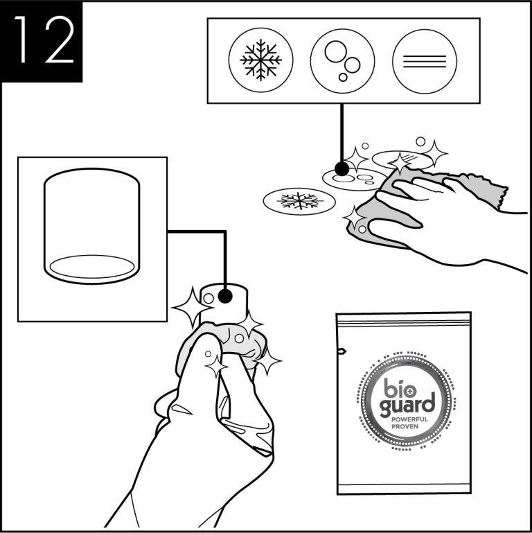
Pay particular attention to the dispense faucet and the push button controls. For this use Sterizen External Sanitiser and Sanitising Wipes.
Remember to include the drip tray. If a Waste Overflow System is fitted, empty this and flush through with a small amount of sanitisation fluid if needed.
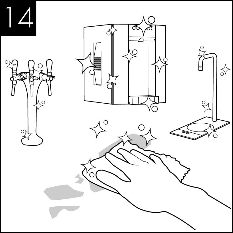
Attend to any cosmetic marks as needed. For this we recommend the use of Bioguard External Sanitiser.
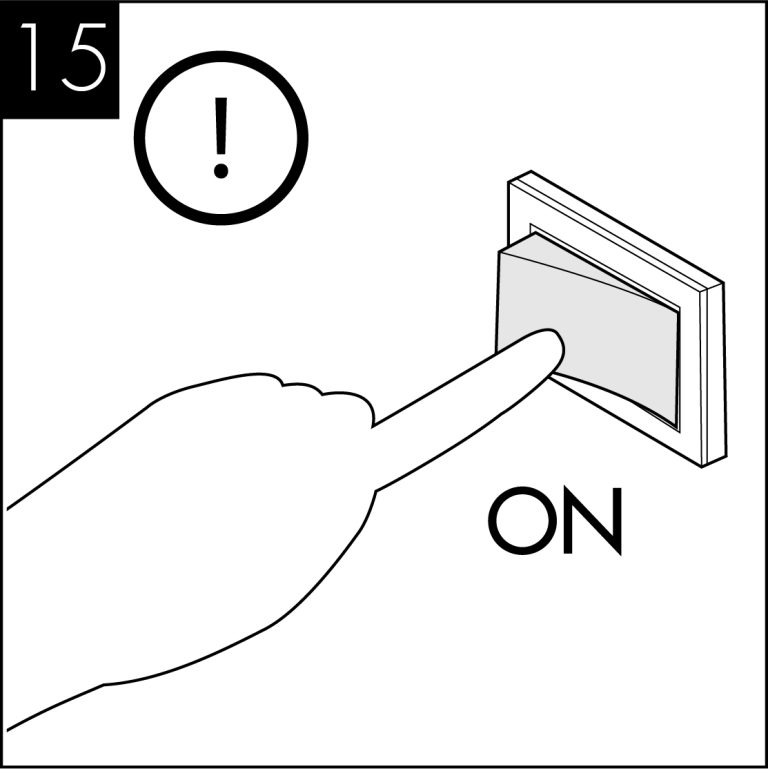
Reconnect the power and switch on the dispenser.
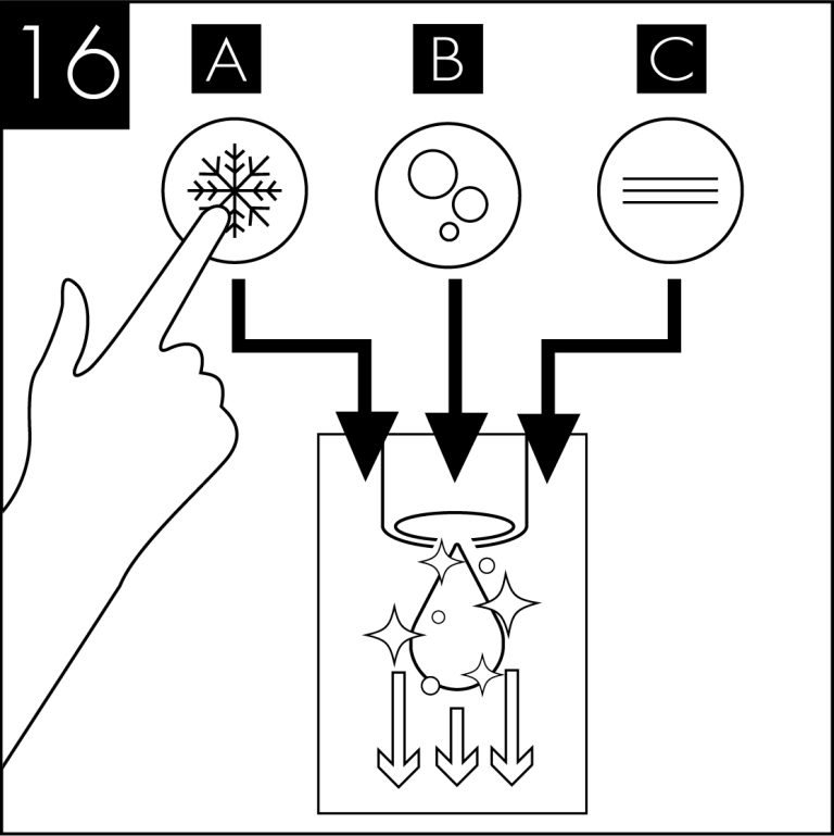
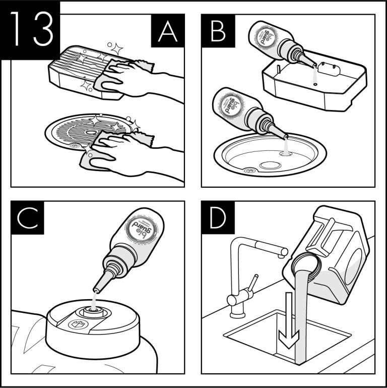
When the external cleaning (minimum 5 minutes) is completed, flush the machine using the chilled button with clean water until the dispense water runs clear. Repeat briefly with the ambient and sparkling buttons if present.
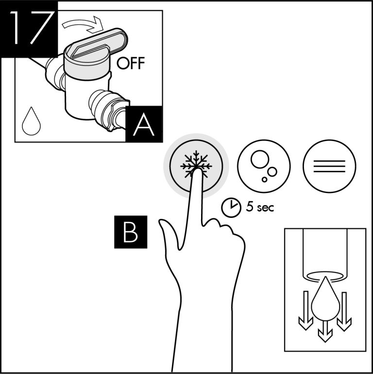
Turn off water and briefly press chilled dispense button to release internal water pressure from the machine.
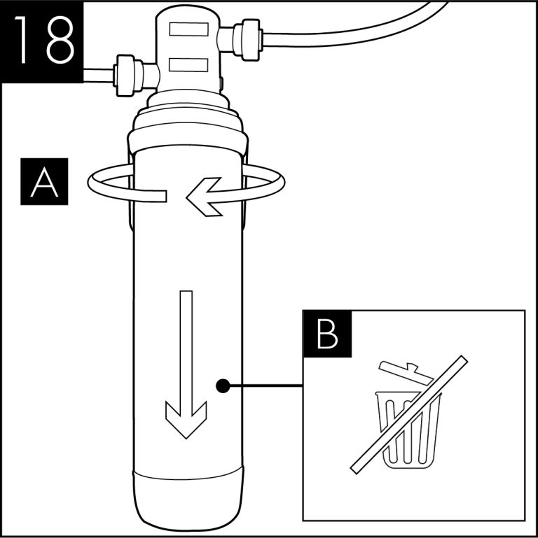
Remove the service filter. Retain service filter for reuse.
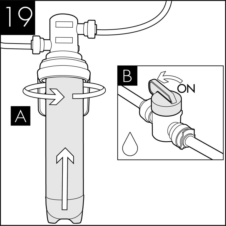
Fit new filter and turn on incoming water supply.
Pre-flush the new filter to waste using the chilled button until the water appears clear and is free of air. Flush through a small amount of water to check all functions.
  | Please note that this sanitisation fluid contains an active caustic/alkaline agent. Always use responsibly and with care remembering that due to its alkaline nature unnecessary concentrated/prolonged contact with any materials, including metals, can cause damage. Always rinse all contact surfaces after use with clean water. |   | Avoid skin contact and wear protective gloves when handling sanitisation fluids. In the event of any skin contact, flush immediately with clean, cold water. |
20-Litre - Draining the Direct Chill Tank

Please make sure the machine is completely disconnected from electricity before carrying out any maintenance work.

Turn off the water supply.

To drain the Direct Chill tank, remove the cap on the drain port at the back of the machine. We recommend it is refitted immediately upon draining being completed.
20-Litre - Emptying the CO2 Tank

Turn off the water supply.

Switch off the Carbonation System switch on the back of
the unit.

Press and hold the Sparkling water dispense button until all the water is expelled and only CO2 gas is being released.

The tank is empty of sparking water when only CO2 is being released.

Ensure to release the Sparkling water button and take care to avoid releasing excess amounts of CO2 gas as this may damage the tank.
30-Litre - Emptying the CO2 Tank
NOTE: Chilled & Ambient models do not drain. Direct Chill water is situated in a factory sealed tank.

Turn off the water supply.

Press and hold the Sparkling water dispense button until all the water is expelled and only CO2 gas is being released.

The tank is empty of sparking water when only CO2 is being released.

Ensure to release the Sparkling water button and take care to avoid releasing excess amounts of CO2 gas as this may damage the tank.
60-Litre - Draining the Direct Chill Tank

Please make sure the machine is completely disconnected from electricity before carrying out any maintenance work.

Turn of the water supply.

Remove the top cover of the water dispenser.

Siphon the water from the cold tank into a suitable container.
60-Litre - Emptying the CO2 Tank

Turn off the chilled and sparkling switch at the rear of the machine. Ensure the solenoid box is still turned on.
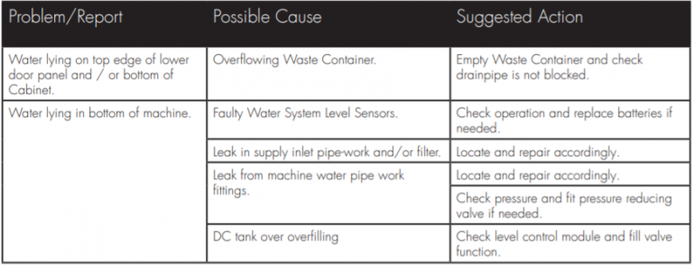
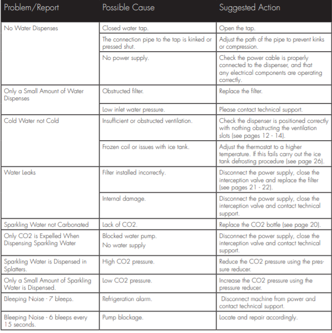
Advanced Troubleshooting
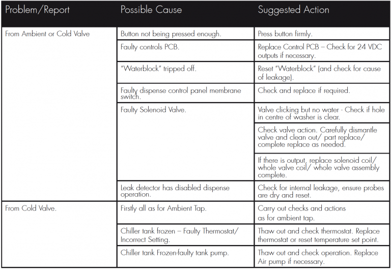
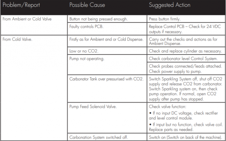
20-Litre - Fault Diagnosis: No Water Dispenses
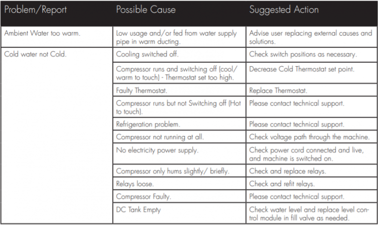
20-Litre - Fault Diagnosis: Water Dispenses but not correct Temperature
20-Litre - Fault Diagnosis: Water Leaks
20-Litre - Fault Diagnosis: Miscellaneous
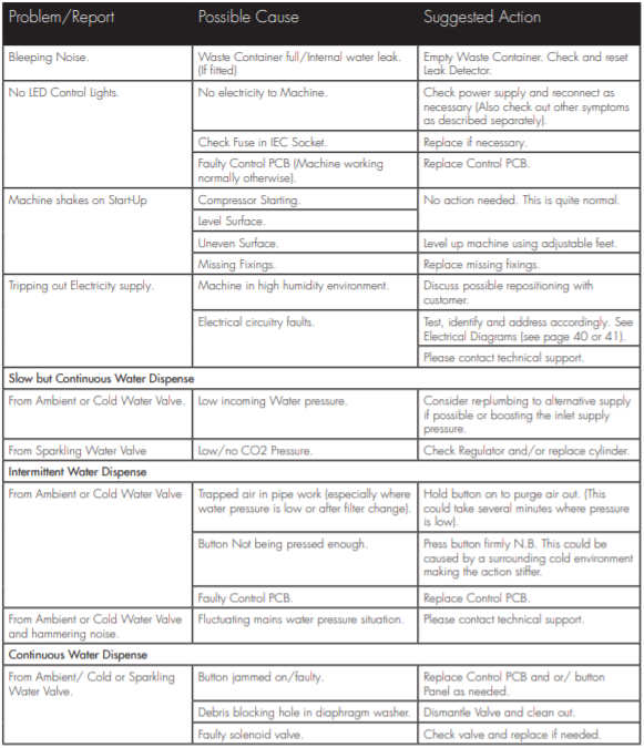
30 & 60-Litre Fault Diagnosis
Exploded Diagrams
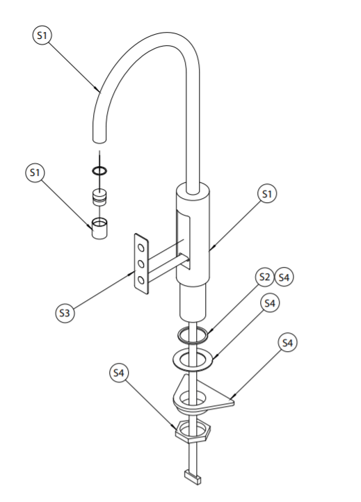
Tap Exploded Diagram
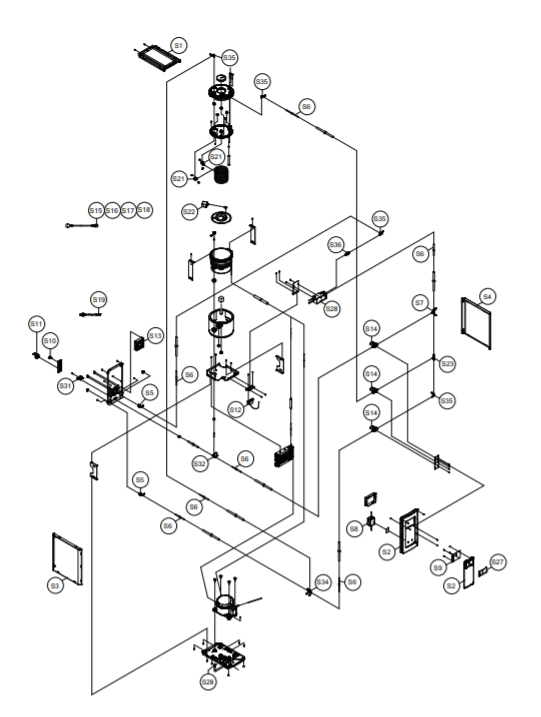
20-Litre - Chilled & Ambient Exploded Diagram
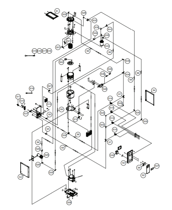
20-Litre - Chilled, Ambient & Sparkling Exploded Diagram
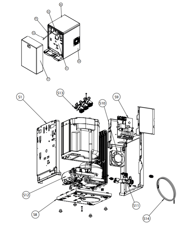
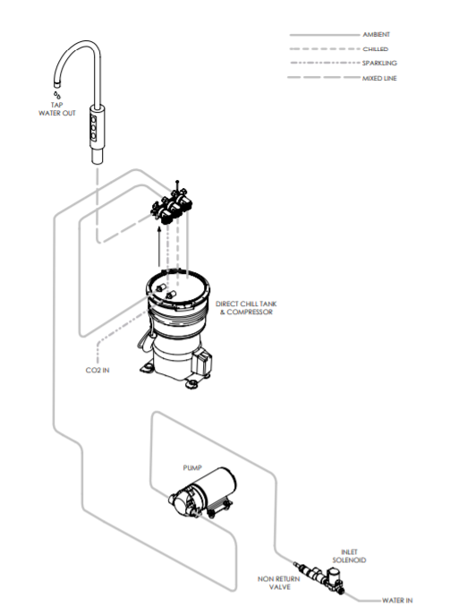
30-Litre - Chilled, Ambient & Sparkling Exploded Diagram
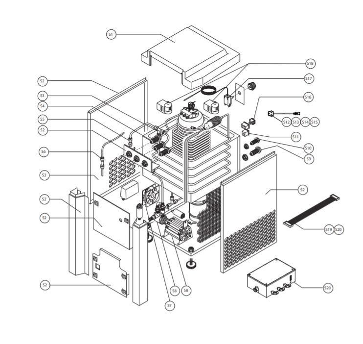
60-Litre - Chilled, Ambient & Sparkling Exploded Diagram
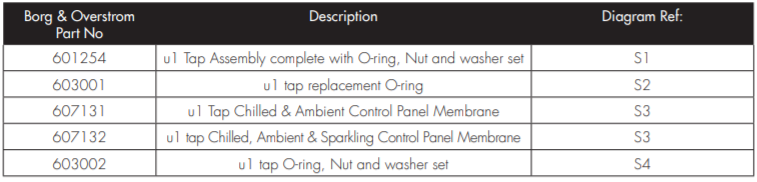
Tap Parts List
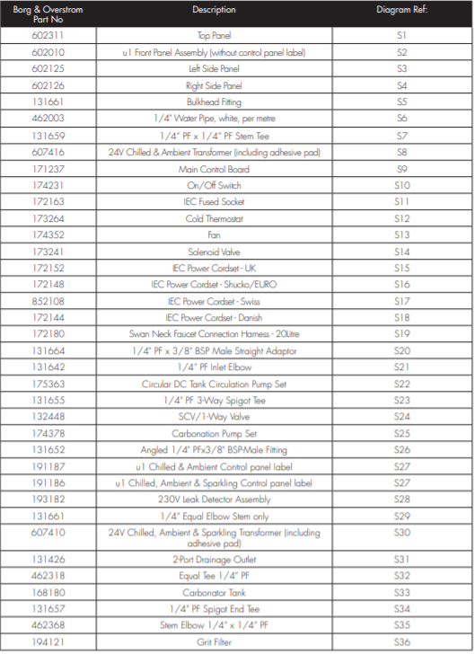
20-Litre - Parts List
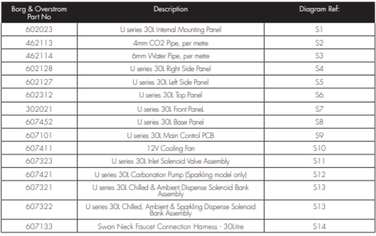
30-Litre - Parts List
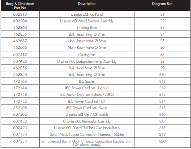
60-Litre - Parts List
Technical Information
Specification (20Litre)
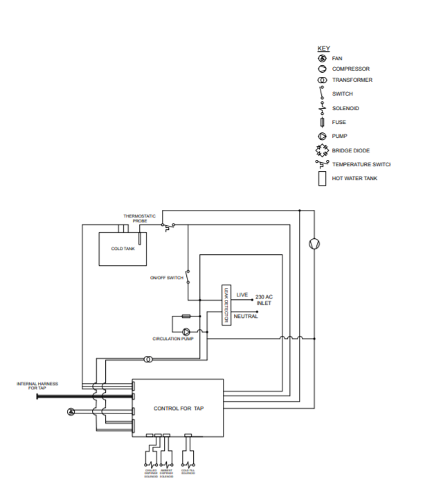
20-Litre - Chilled & Ambient Electrical Circuit Diagram
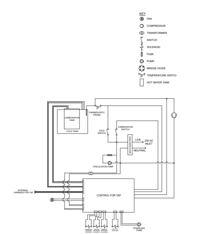
20-Litre - Chilled, Ambient & Sparkling Electrical Circuit Diagram
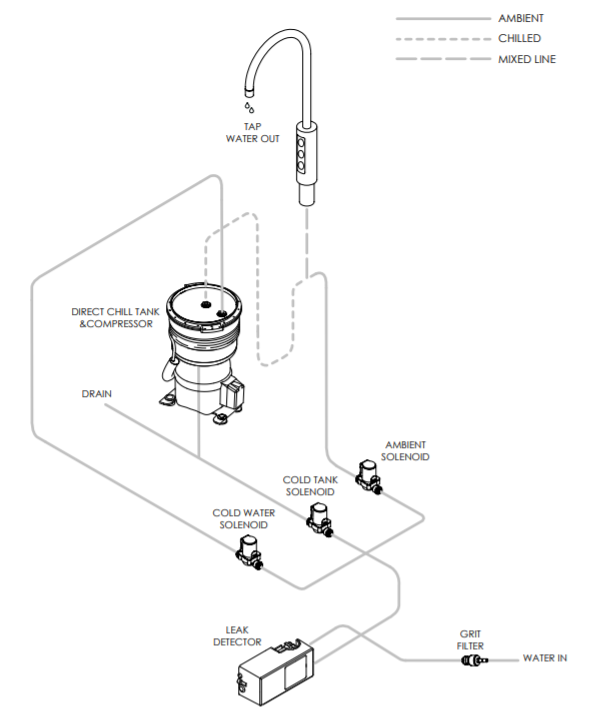
20-Litre - Chilled & Ambient Water Pathway Diagram
20-Litre - Chilled, Ambient & Sparkling Water Pathway Diagram
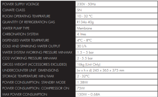
30-Litre - Technical Information
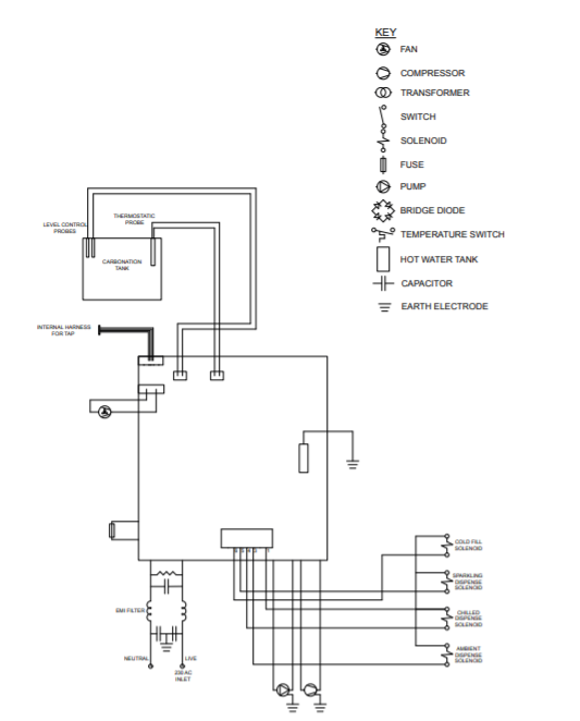
30-Litre - Electrical Circuit Diagram
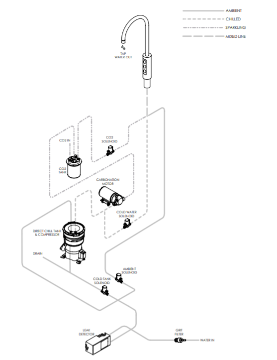
30-Litre - Water Pathway Diagram
60-Litre - Technical Information
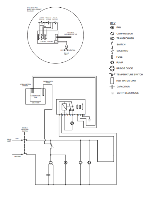
60-Litre - Electrical Circuit Diagram
60-Litre - Water Pathway Diagram