U1.S2 Install & Operation Manual
Model Overview
Introduction
The u1 epitomises cutting-edge design and innovation with its contoured tap and compact under-counter unit. This is our most discreet range and will fit into any environment seamlessly.
The under-counter dispenser is a Dry Chill™ cooler designed to
provide ambient still, chilled and/or carbonated water. All the materials and components are tested during the entire production process in order to satisfy all expectations.
| COOLING SYSTEM | Stainless steel direct chill coil encased in a solid-block system for instant response cool down action. Ultra efficiency compression system with capillary control. Environmentally friendly R134a refrigerant. |
| COLD TEMPERATURE | 2°C - 10°C. |
| OUTPUT PER HOUR | 40 litres cold at <10°C. |
| 40 litres sparkling at <10°C. | |
| DISPENSE | Swan Neck Faucet with ergonomically designed and situated light touch sensitive controls. |
| MAXIMUM RUNNING POWER CONSUMPTION - CHILLED, AMBIENT & SPARKLING | 570 watt (during recovery), Rated input 323 watt. |
| MAXIMUM RUNNING POWER CONSUMPTION - CHILLED & AMBIENT | 570 watt (during recovery), Rated input 300 watt. |
| POWER SUPPLY | 230V AC (50 Hz). |
| WATER CONNECTION | Mains in - 1/4” Push Fit/ Faucet - 1/4” Push Fit. |
| C02 CONNECTION | 1/4” Push Fit. |
| DIMENSIONS | (w x d x h) 330 x 370 x 362mm. |
| WEIGHT | 26Kg. |
| CUPBOARD VENTILATION | Required. |
Component /Feature Overview
U1 Tap - Major Components

Please Note: Mains Installation Kit & Filters are supplied as extra items according to individual ordering requirement.
S2 Electronic - Major Components

Installation
Tap Installation


When planning and providing for the connection to the
services, always allow for easily accessible service isolator fittings and for the position of an external water filter.

Identify a suitable position for the swan neck faucet. A 33-35mm (max) hole is required.

When positioning to drain over an existing sink bowl, allow for the reach of the swan neck or otherwise the position of any optional drip tray.

Also allow for the height of the swan neck under any
overhanging cupboard/shelf.

Allow for the space needed for forming the required hole. Relate the selected position to the underneath of the counter and check for any obstructions.

Allow sufficient space for fitting the back nut to the faucet stem.

Carefully form the needed hole using the correct type of cutter for the work surface material.
Observe all local occupational health and safety requirements.

Remove the back nut and washer from the faucet and carefully feed the connecting pipe tail and ribbon cable through the hole formed in the work surface. Ensure the sealing O ring is prefitted in the base of the faucet. You may want to apply a thin bead of silicone sealant also.

With the faucet control panel in the right position, carefully refit the back washer and nut. Take care not to over-tighten.

Install the ventilation system using the instructions/templates provided.

Fit optional Drip Tray at this stage (if selected).

Once the ventilation system is installed, position the unit on the ducting as instructed and follow the connection steps – see Ventillation System Installation Steps
Tap Dimensions

Driptray Dimensions

Ventilation System Installation
When Borg & Overström undercounter units are installed inside a cabinet or housing, adequate ventilation is recommended to ensure that they operate satisfactorily.
During a cooling cycle it is normal for the unit to produce heat, and the purpose of ventilation is to provide a supply of air that can absorb the generated heat which would otherwise accumulate inside the cabinet or housing, and reduce the cooling performance of the unit.
The amount of heat generated by the cooling cycle depends directly upon the amount of usage – the higher the usage, the more heat produced.
To provide adequate ventilation we recommend that air grilles/vents are fitted as supplied (or vent apertures formed) in the cabinet to allow an airflow as shown below. Normally this should be enough for all situations.
Important: Before making any cuts into the cupboard or kick board, ensure the area to be cut is free from water pipes or electrical cables. There is a risk of serious injury or death if electrical cables are cut, and significant damage to property if a water pipe is cut.

Using the template provided, carefully mark and cut the aperture to the edge of the cabinet.

Situate the Simple-fit ventilation base in place centrally over the aperture. Ensuring that there is a minimum of 30mm air gap to each side.


The S2 appliance must be placed carefully in position on the ventilation base to ensure the chimney is located correctly in the chimney aperture at the rear of the base. After installation the vents at the front of the cabinet and to the sides of the ventilation base must not be obstructed. Any obstructions will adversely affect the airflow to the appliance causing potential for poor performance, over heating or fridge failure.
Undercounter Installation & Water Connection

Locate the machine in a suitable enclosure, ensuring
that the supplied ventilation kit can be installed.

Connect the u1 tap to the water outlet.

Connect the faucet connection harness to the tap control panel membrane.

Install within connection box as supplied.

*Connect the CO2 supply from gas regulator, ensuring
the pressure is set to max 58 PSI (4 bar), and turn on the supply.

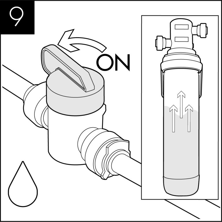
Connect the chiller to the water supply and open the mains supply isolation valve.

Connect the unit to the electrical supply and turn on.

After approximately 10 minutes, the compressor and
fan will stop as the chiller has reached its normal operating temperature.

*The carbonator should be purged of air by activating the sparkling water dispense for approximately 20 seconds.

*Isolate the water supply and activate the sparkling
water dispense. When the water system has emptied,
allow gas to be expelled for approximately 5 seconds.
Immediately after this 5 second period restore the water supply and allow the system to refill.

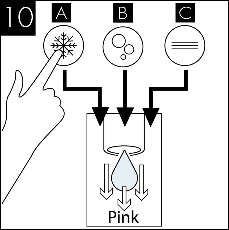
Dispense ambient, still and sparkling water, in turn,
to purge any air from the system. The time to do this
may vary depending on the length of pipe between the
unit and the tap.

Safety
The unit should be isolated from the electricity supply before removal of any covers.
Great care must be employed when working with high pressure carbon dioxide, andin no cases should the maximum operating pressure of 58 PSI (4 bar) be exceeded.
Sparkling Water Flow Rate - Sparkling Versions Only
NOTE: The soda water flow rate is set to 35ml/sec at a CO2 pressure of 58 PSI (4 bar). To adjust the soda water flow rate follow these steps:

Remove the 3 screws holding the unit lid down and lift the lid away.

Locate the flow control adjuster, this can be found on top of the carbonator can, connected to the central port of the can.

Loosen the lock nut, but do not remove.

Flow can then be adjusted by turning the adjuster screw, anti-clockwise to increase flow and clockwise to restrict flow. After each adjustment the flow rate should be timed.
Once the correct flow rate is achieved reverse steps 1, 2 and 3.
General Safety

Cutting Templates
Simple-Fit Vent Base Cutting Template
We recommend you check the dimensions of the ProCore Simple-fit Ventilation Kit using the cutting template prior to cutting the base cabinet.
Download or order the ProCore Vent Base Cutting Template here
Operation
Functions & Controls
Tap Control Panel

Eliwell Control Panel

Controls

Basic Settings
Adjusting the Set Point:
1. Switch on Mains power – the display will flash several times, then the fridge system will switch on and the display will give a steady reading, this is the temperature of the water bath sensor.
2.Press and release the ‘Set’ button – The
display will show ‘SET’.

3. Press ‘Set’ again and the display will show
a numeric value (e.g. 9°C).
4. Raise or lower this figure to the desired setting using the up or down arrows on the left of the control display window.
5. When the correct setting is shown in the display window press ‘Set’ button the display will now show SET.
6.Press FNC button to return to the probe temperature reading.
Altering the Differential setting:
1. Press and hold the ‘Set’ button until CP shows on the display – Release the button.
2. Press ‘Set again, DIF will show on the display.
3. Press ‘Set’ again and the display will show a numeric value, (e.g. 1°C, the default setting.)
4. Raise or lower this figure to the desired setting using the up or down arrows on the left of the control display window.
5. When the adjustment has been made press ‘Set’ again the display will show DIF.
6. If no further changes are required press FNC again to exit.
NOTE: If no buttons are pressed for 15 seconds, the control will revert to temperature display mode, and any changes to settings will be saved.
CO2 Bottle Installation - Sparkling Versions Only

Unpack CO2 Regulator and fit elbow fitting to spigot outlet.

Attach the regulator to the disposable CO2 bottle, ensuring the small pressure relief vent in the stem is facing away from you or anyone else. Ensure the regulator is closed. Hand tighten securely.

Connect the assembled CO2 bottle and regulator to the CO2 inlet using a ¼” pipe.

Stand the cylinder in a suitable place.

We recommend between 3.5 – 4 bar(58 PSI) (max). Do not exceed 4 bar pressure.

It is necessary to prime the sparkling system with CO2 – push the sparkling button for a few seconds until CO2 is coming through. Check and adjust the CO2 pressure
accordingly.

Allow the machine to stand for 8 – 12 minutes for the initial chilling process to complete.
Maintenance & Cleaning
Sanitisation Guide
The product is supplied from the factory in clean condition, but we recommend that a sanitisation procedure is caried out at the point of installation, according to the sanitisation instruction relevant to this model, which can be found in the respective Instruction & Operation Manual
NOTE: Failure to use sanitising products and processes approved by Borg & Overström will invalidate your warranty.
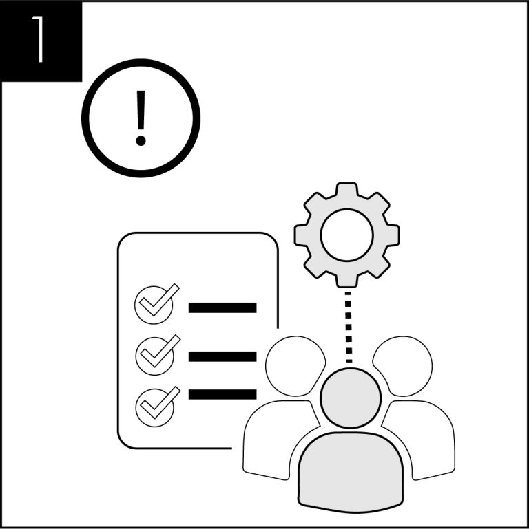
This operation must only be carried out by trained staff.
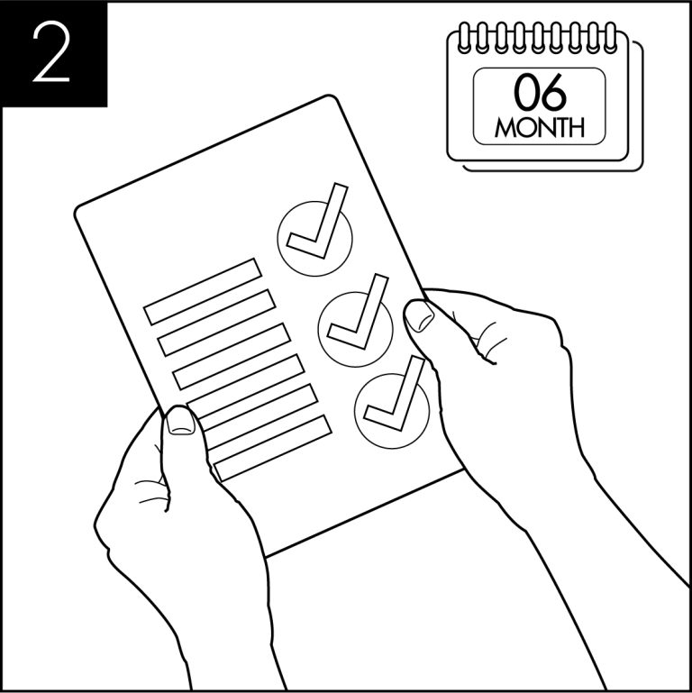
A sanitisation procedure is recommended every 6 months.
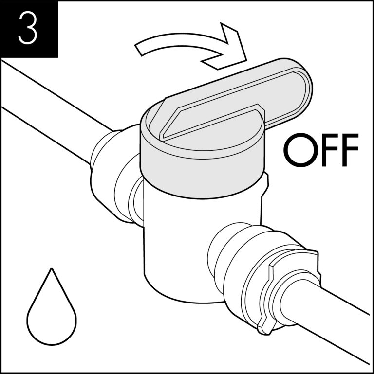
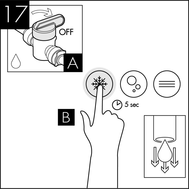
Turn off incoming mains water
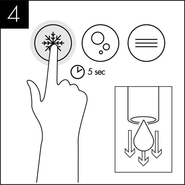
Briefly press chilled dispense button to release internal water pressure from the machine.
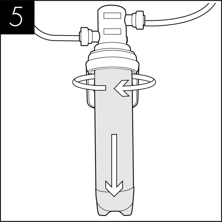
Remove the existing filter
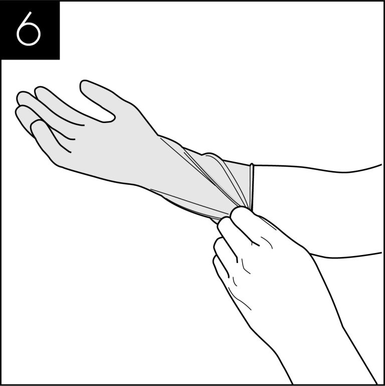
Use hand gel and put on protective gloves.
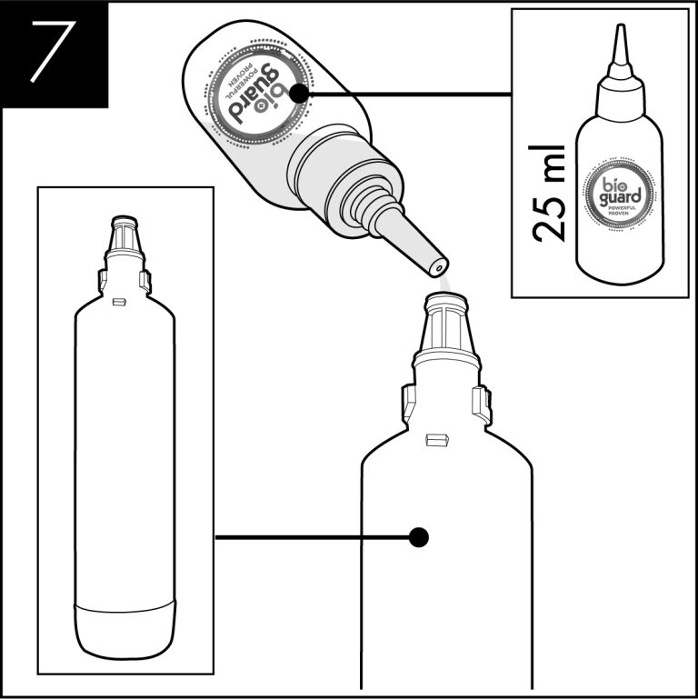
Add 25 ml of Bioguard Internal Sanitising Solution to a clean and empty service filter cartridge.
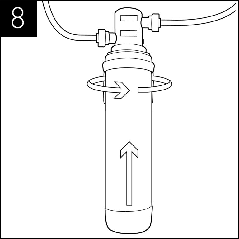
Connect to filter head.
Turn on incoming water, allow the service filter cartridge to fill
Dispense water using the chilled button until the water appears pink. Repeat with sparkling & ambient water buttons.
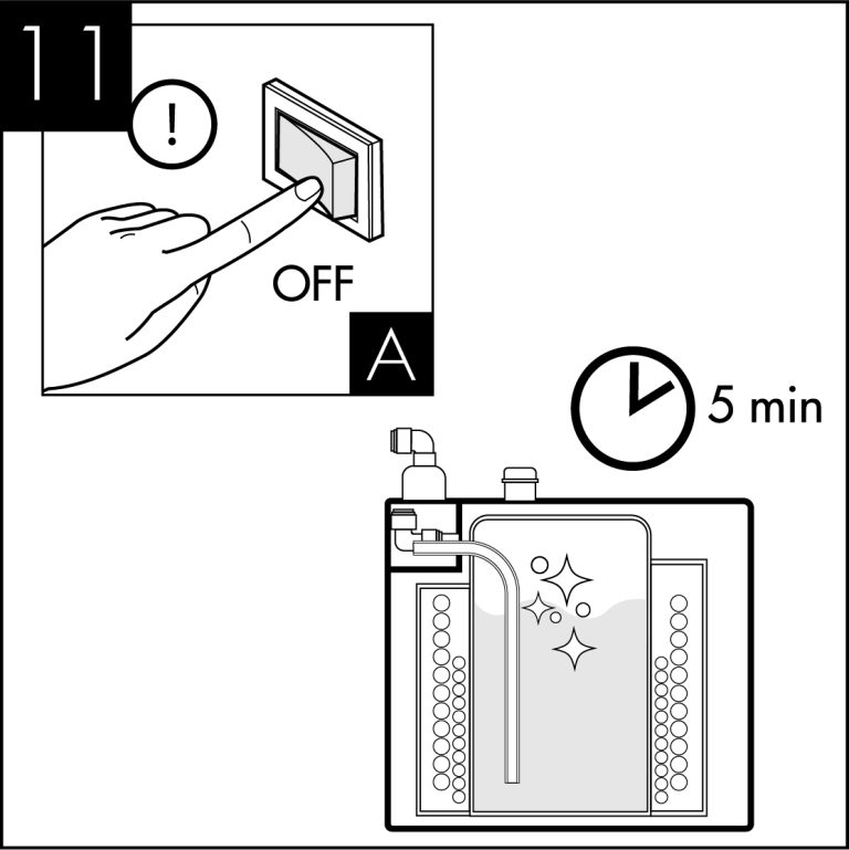
Leave the solution inside machine for sanitisation to take effect (minimum 5 minutes) while thoroughly cleaning the dispenser externally. (All maintenance operations must be carried out with the dispenser switched off.)
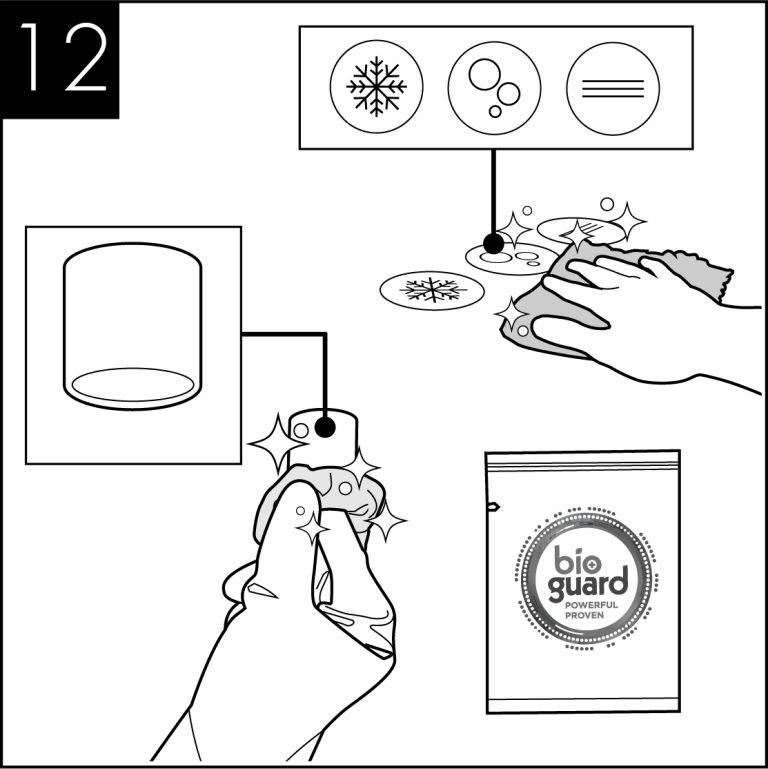
Pay particular attention to the dispense faucet and the push button controls. For this use Sterizen External Sanitiser and Sanitising Wipes.
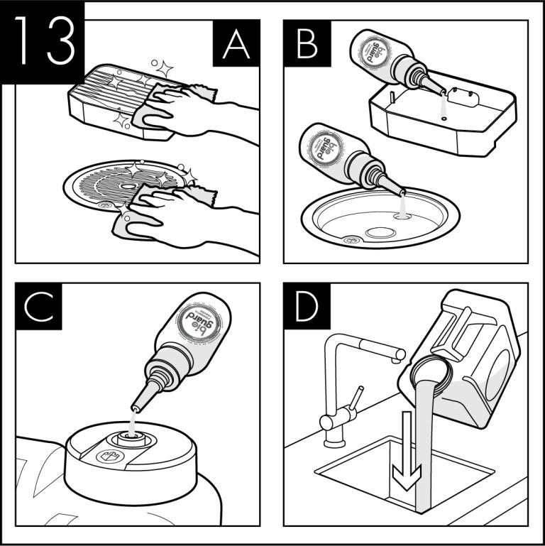
Remember to include the drip tray. If a Waste Overflow System is fitted, empty this and flush through with a small amount of sanitisation fluid if needed.
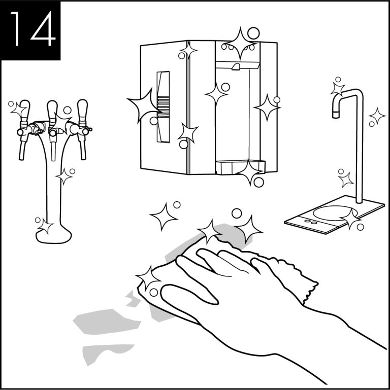
Attend to any cosmetic marks as needed. For this we recommend the use of Bioguard External Sanitiser.
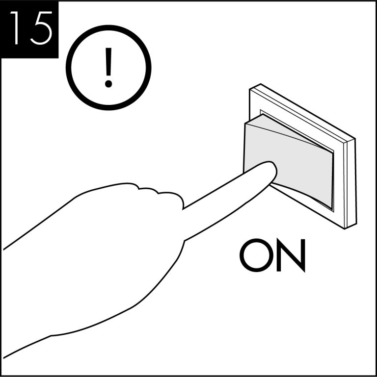
Reconnect the power and switch on the dispenser.
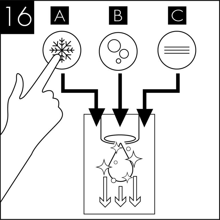
When the external cleaning (minimum 5 minutes) is completed, flush the machine using the chilled button with clean water until the dispense water runs clear. Repeat briefly with the ambient and sparkling buttons if present.
Turn off water and briefly press chilled dispense button to release internal water pressure from the machine.
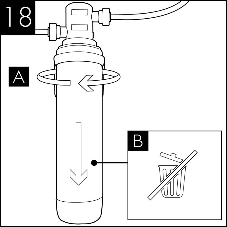
Remove the service filter. Retain service filter for reuse.
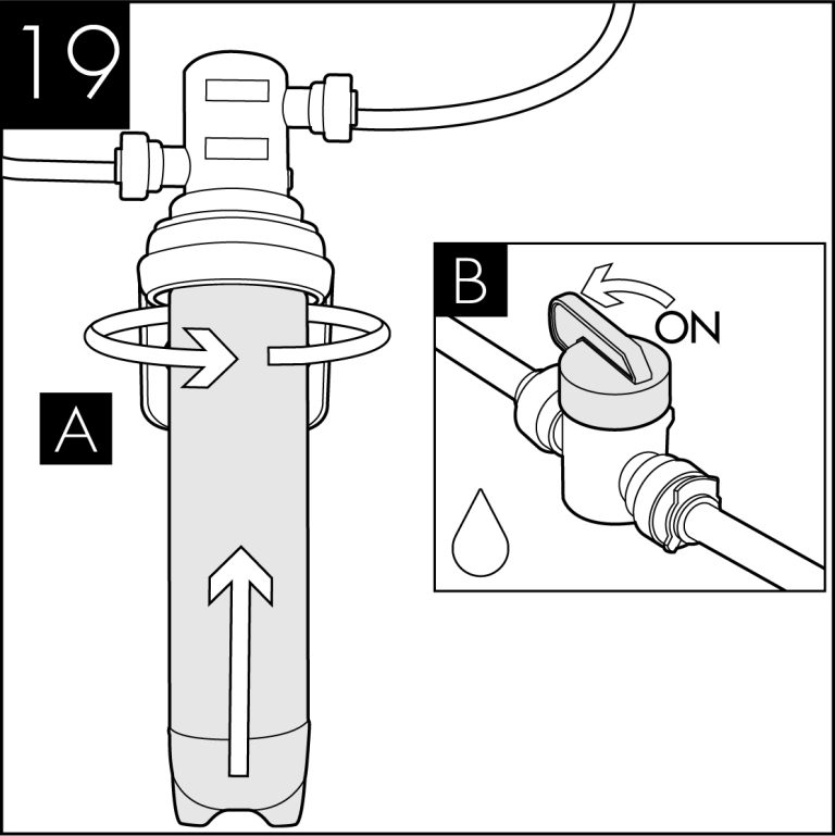
Fit new filter and turn on incoming water supply.
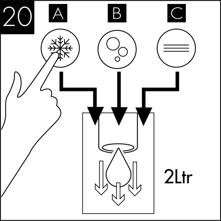
Pre-flush the new filter to waste using the chilled button until the water appears clear and is free of air. Flush through a small amount of water to check all functions.
  | Please note that this sanitisation fluid contains an active caustic/alkaline agent. Always use responsibly and with care remembering that due to its alkaline nature unnecessary concentrated/prolonged contact with any materials, including metals, can cause damage. Always rinse all contact surfaces after use with clean water. |   | Avoid skin contact and wear protective gloves when handling sanitisation fluids. In the event of any skin contact, flush immediately with clean, cold water. |
Emptying the CO2 Tank - Sparkling Versions Only

Turn off the water supply.

Press and hold the Sparkling water dispense button until all the water is expelled and only CO2 gas is being released.

The tank is empty of sparking water when only CO2 is being released.

Ensure to release the Sparkling water button and take care to avoid releasing excess amounts of CO2 gas as this may damage the tank.
Advanced Troubleshooting
Fault Diagnostics
| Problem/Report | Possible Cause | Suggested Action |
|---|---|---|
| No Water Dispensing | Water Pressure Regulator | Check water tank flow through the regulator. Replace if necessary. |
| No Sparkling Water* | No CO2 pressure, check by operating pressure relief valve on carbonator tank. | Check CO2 bottle, regulator and nonreturn valve. Supply pressure should be 58 psi (4bar), adjust or replace as necessary. |
| Carbonator Tank Not Filling | Check carbonator probe for possible short circuit to ground. Check for pump timeout, cycle power off & on then purge carbonator. Check supply to water pump (230V AC), if voltage present & pump inoperative - replace pump. If voltage not present & pump is not timed out, check control board fuses. If necessary replace control board. | |
| Poor Quality Carbonation* | Incorrect CO2 Pressure | Check CO2 bottle, regulator and nonreturn valve. Supply pressure should be 58 psi (4bar), adjust or replace as necessary. |
| Air in Carbonator Tank | Isolate the power supply and operate the sparkling water tap until gas is expelled. Allow gas to expel for 5 seconds. Switch on power supply and allow the tank to refill. | |
| Residue in Carbonator Tank | After prolonged use, a surface film can develop within the carbonator tank. Refer to cleaning and sanitising instructions. | |
| Carbonator Tank is Overfilled | If pump runs continuously, check connections to tank level probe, if problem persists replace the PCB. |
Fault Diagnostics (Continued)
| Problem/Report | Possible Cause | Suggested Action |
|---|---|---|
| Warm Drinks | Insufficient cooling air flow through the fridge. | Check that the condenser is not blocked. Check supply to cooling fans (230V AC). If supply present replace fans. If supply not present move on to the compressor. The supply to the fans and the compressor are linked. |
| Compressor not running | Check supply to compressor (230V AC). If supply not present check the Eliwell fridge controller is operating. Check for system over heat. Allow the unit to cool and check for airflow obstructions. Once the unit has cooled the fridge system will restart. If the problem persists contact technical support. If the Eliwell controller is operating check the operating parameters are correctly set and inspect the probes. Replace probes as necessary. | |
| Eliwell fridge controller not operating. | Check supply to the controller. If present replace the controller. If supply is not present check the PCB. | |
| PCB not operating. | Check the fuses on the board and the fuse in the mains plug. If fuses are ok replace the PCB. | |
| Fridge failure | If compressor & fan are running and there is no cooling contact technical support. |
Exploded Diagrams
U1 Tap
| Part number: | Description: | |
|---|---|---|
| 607131 | U1 Tap Chilled & Ambient Control Panel Membrane | View in store |
| 604001 | U1 Swan Neck Tap Aerator Set | View in store |
| 601254 | U1 Tap Assembly complete with O-ring, Nut and washer set | View in store |
| 603001 | U1 tap replacement O-ring | View in store |
| 603002 | U1 tap O-ring, Nut and washer set | View in store |
| 607132 | U1 tap Chilled, Ambient & Sparkling Control Panel Membrane | View in store |
S2 Undercounter
| Part number: | Description: | |
|---|---|---|
| 637325 | Flow Control | View in store |
| 637408 | Axial Fan 240V | View in store |
| 637106 | Solenoid Dispense Control Board | View in store |
| 637324 | 3 Way Dispense Solenoid | View in store |
| 637425 | Aquatec Pump IPC1400 MOTOR ASSEMBLY | View in store |
| 462359 | Equal Tee, 3/8 | View in store |
| 462874 | Reducing Straight Connector, 5/16-1/4 | View in store |
| 462362 | Equal Elbow, 3/8 | View in store |
| 462371 | Stem Elbow, 3/8-3/8 | View in store |
| 172180 | Swan Neck Faucet Connection Harness | View in store |
| 632032 | S2 Lid | View in store |
| 462376 | Equal Elbow, 5/16 | View in store |
| 462327 | Reducing Elbow 3/8 x 1/4 | View in store |
| 462384 | Stem Elbow, 5/16-5/16 | View in store |
| 462368 | Stem Elbow, 1/4-1/4 | View in store |
| 462325 | Bulkhead Connector, 1/4 | View in store |
| 462318 | Equal Tee, 1/4 | View in store |
| 462364 | Stem Adaptor, 3/8ODx1/4BSP | View in store |
| 462369 | Stem Elbow, 3/8-1/4 | View in store |
| 462374 | Reducer, 3/8-5/16 | View in store |
| 462313 | Straight Adaptor, 3/8x1/4 BSP | View in store |
| 637417 | 12V Power Supply | View in store |
| 637326 | Eliwell Control | View in store |
| 632031 | S2 Front Wrap | View in store |
| 637107 | EXL170 CLIP III Control Board | View in store |
| 462667 | Single Check Valve, 5/16 | View in store |
| 462014 | 5/16 LLDPE BU TUBE | View in store |
| 462013 | 1/4 LLDPE BU TUBE | View in store |
| 633512 | Can Wrap Insulation | View in store |
| 462668 | Single Check Valve, 1/4 | View in store |
| 462012 | 3/8 LLDPE BU TUBE | View in store |
| 461358 | S2 Pressure Regulator Valve | View in store |
| 607323 | 2 Way Dispense Solenoid | View in store |
Technical Information
Chilled, Ambient & Sparkling - Circuit Diagram

Chilled & Ambient - Circuit Diagram

Chilled, Ambient & Sparkling - Water Pathway Diagram

Chilled & Ambient - Water Pathway Diagram

Specification
| COOLING SYSTEM | Stainless steel direct chill coil encased in a solid-block system for instant response cool down action. Ultra efficiency compression system with capillary control. Environmentally friendly R134a refrigerant. |
| COLD TEMPERATURE | 2°C - 10°C. |
| OUTPUT PER HOUR | 40 litres cold at <10°C. |
| 40 litres sparkling at <10°C. | |
| DISPENSE | Swan Neck Faucet with ergonomically designed and situated light touch sensitive controls. |
| MAXIMUM RUNNING POWER CONSUMPTION - CHILLED, AMBIENT & SPARKLING | 570 watt (during recovery), Rated input 323 watt. |
| MAXIMUM RUNNING POWER CONSUMPTION - CHILLED & AMBIENT | 570 watt (during recovery), Rated input 300 watt. |
| POWER SUPPLY | 230V AC (50 Hz). |
| WATER CONNECTION | Mains in - 1/4” Push Fit/ Faucet - 1/4” Push Fit. |
| C02 CONNECTION | 1/4” Push Fit. |
| DIMENSIONS | (w x d x h) 330 x 370 x 362mm. |
| WEIGHT | 26Kg. |
| RATED CURRENT - CHILLED & AMBIENT | 1.9A |
| RATED CURRENT - CHILLED, AMBIENT & SPARKLING | 2A |
| FUSE RATING | 5A |
| INLET WATER PRESSURE | 22 PSI (1.5Bar) Internally regulated to 22 PSI (1.5Bar). |
| CO2 PRESSURE | 58 PSI (4 Bar) Maximum |
| COMPRESSOR | Tecumseh THB4422Y |
| CLIMATIC CLASS | N |