- Model Overview
- Installation & Operation Guide (CW698)
- Installation & Operation Guide (DC698)
- Installation & Operation Guide (CW628)
- Cup Dispenser
- Leak Detector
- Installing the Level Sensor
- The Waste Kit
- Sanitisation Guides
- Descaling Guides
- Trouble Shooting Guides
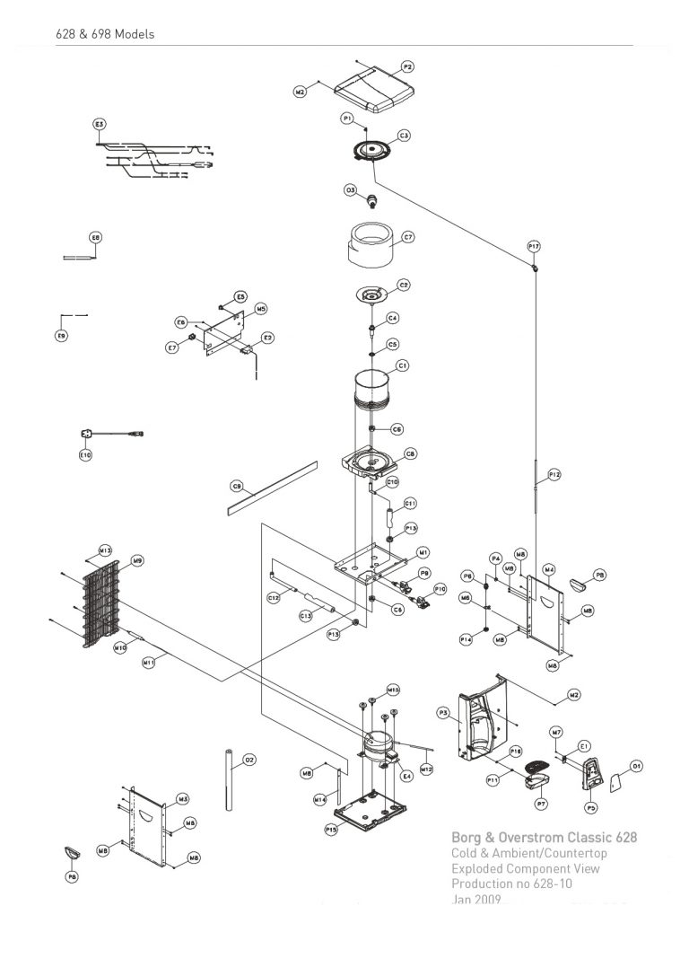
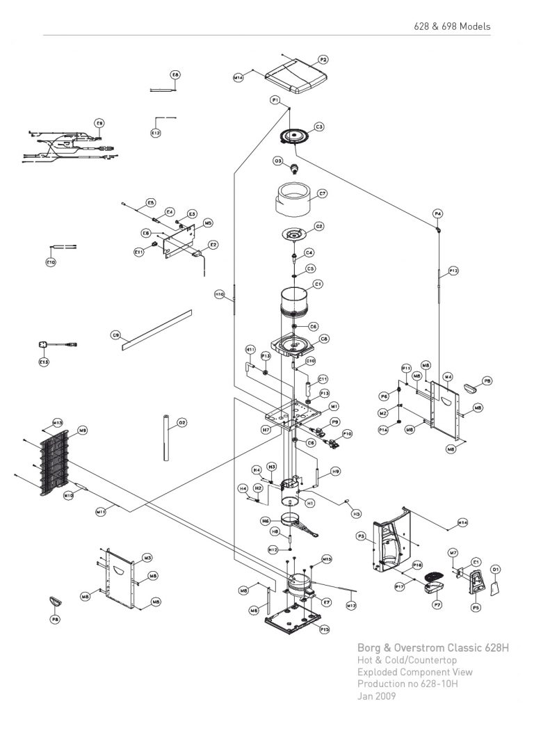
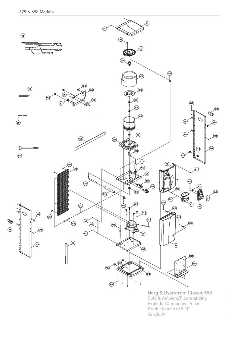
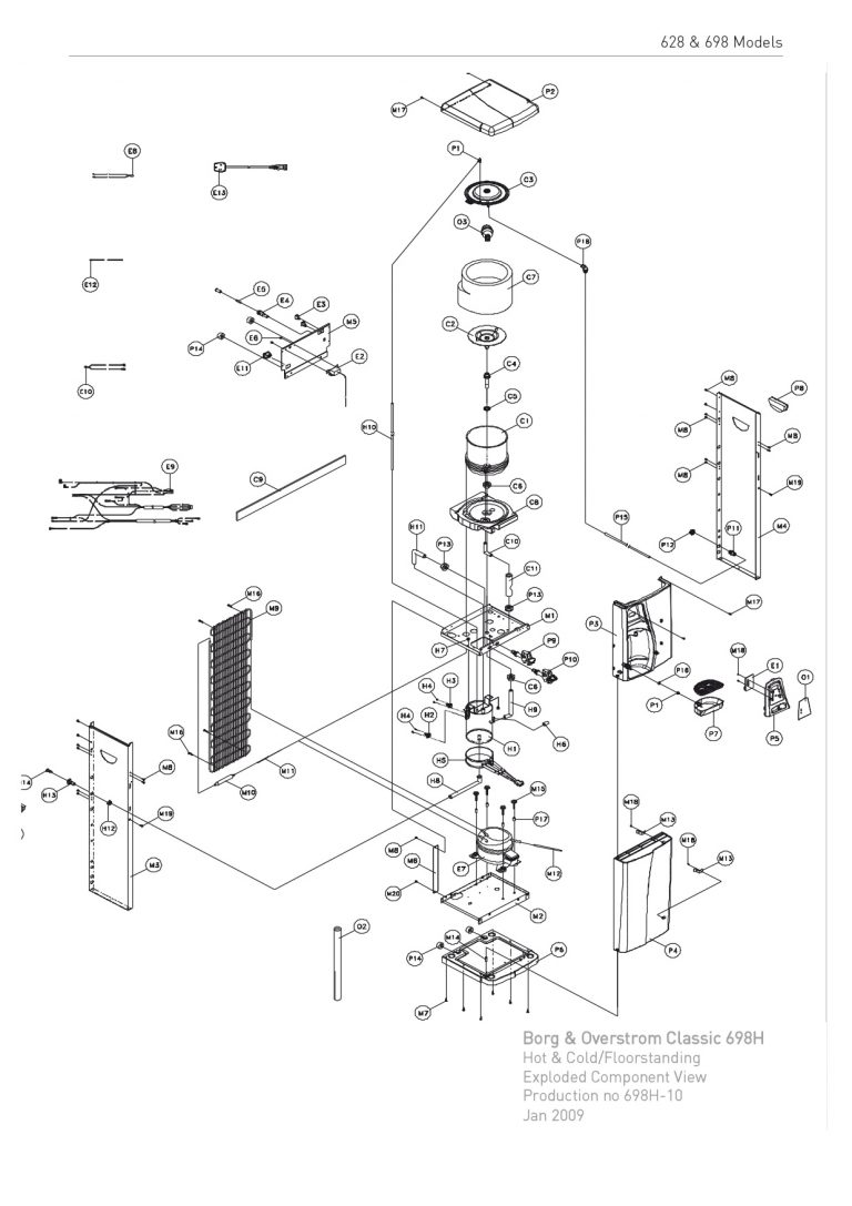
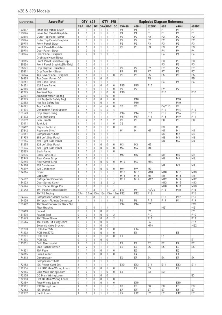
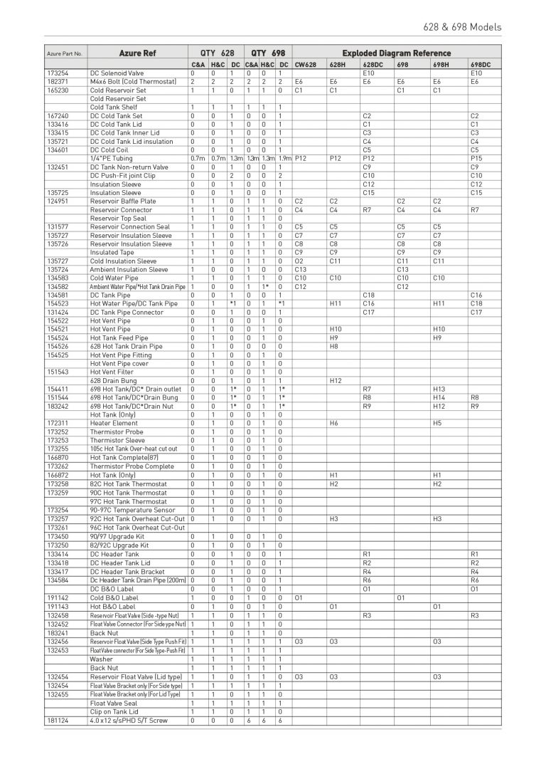
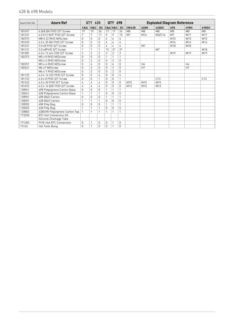
- Exploded Diagrams
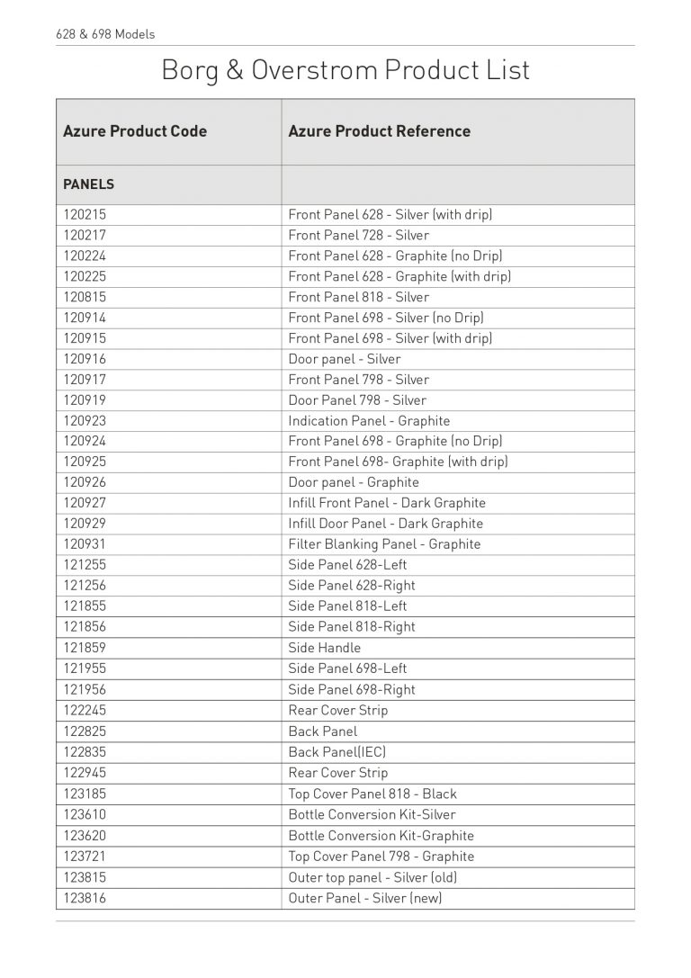
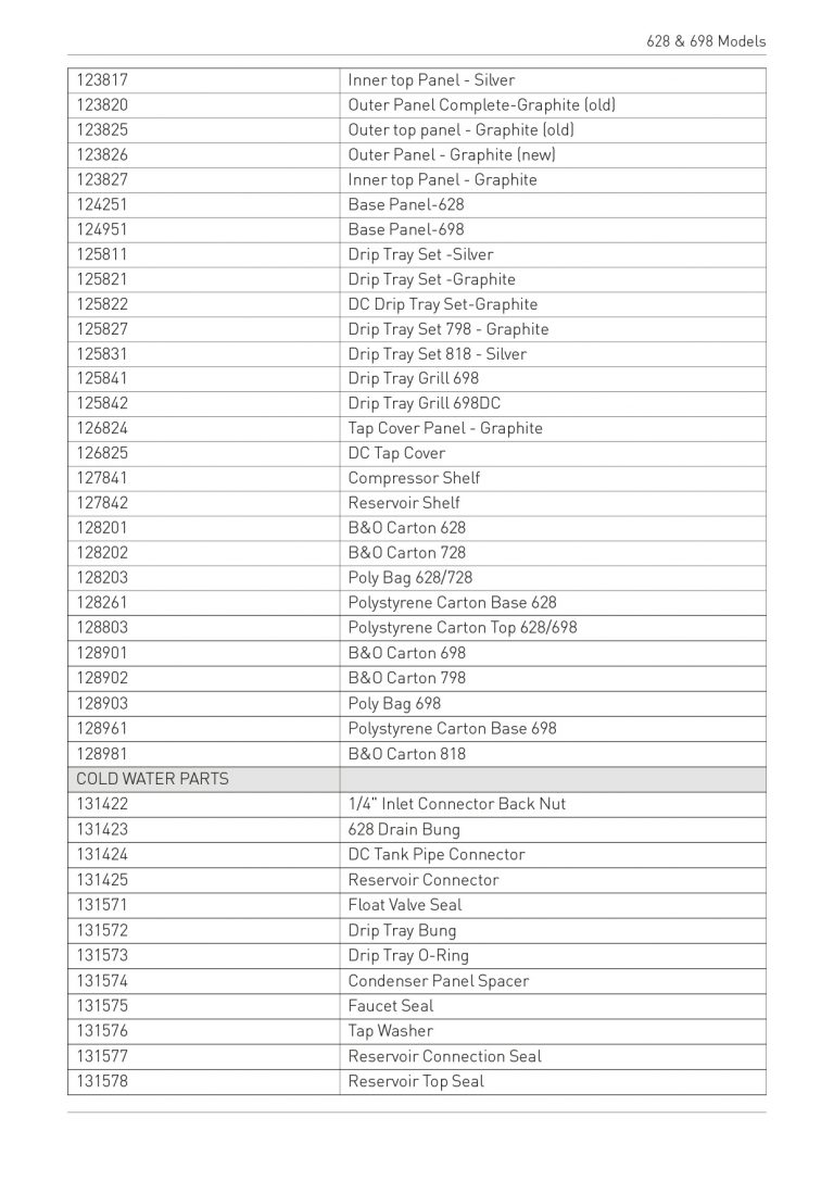
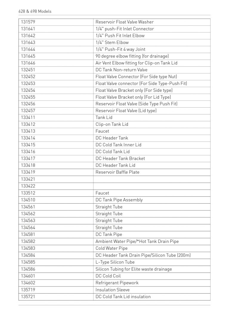
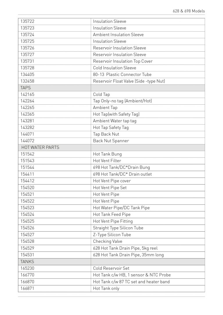
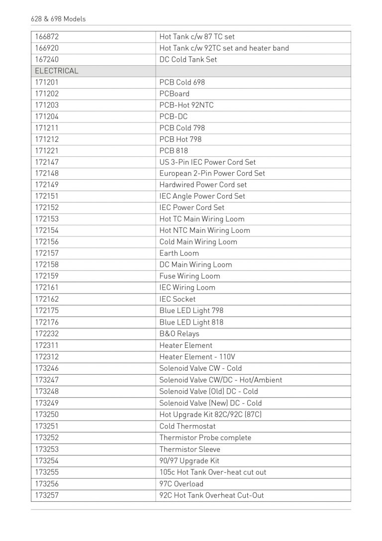
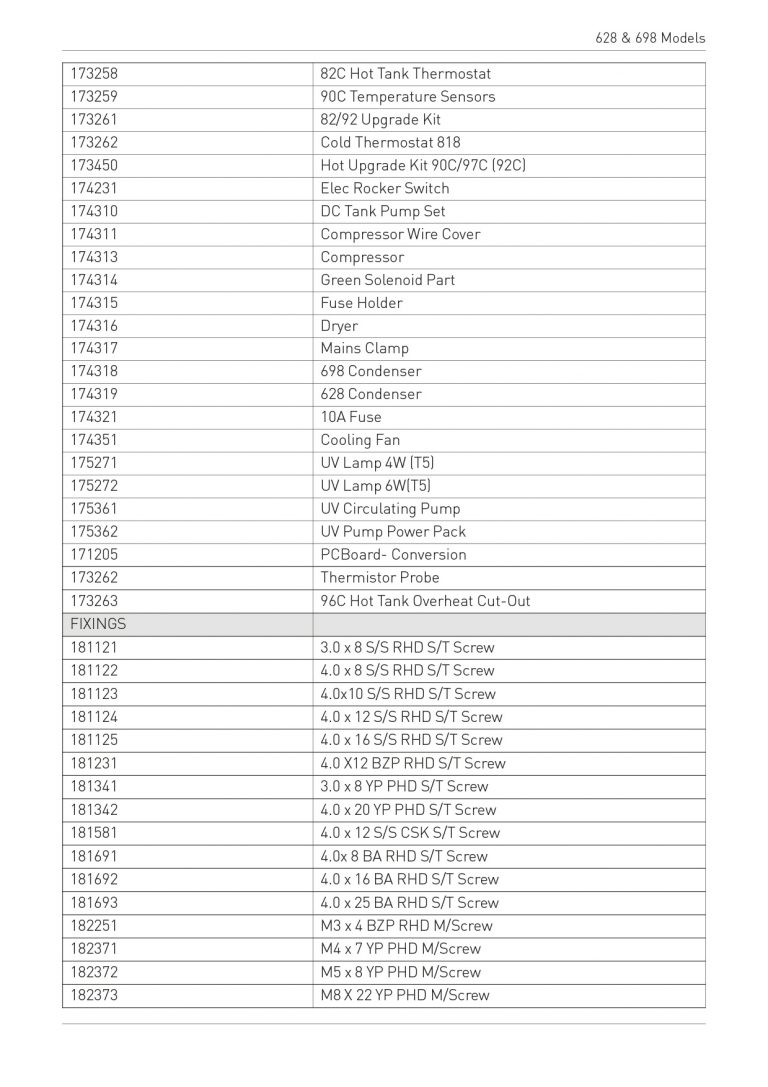
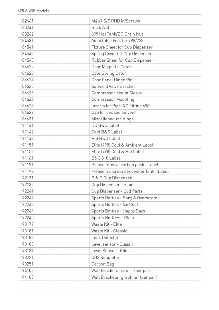
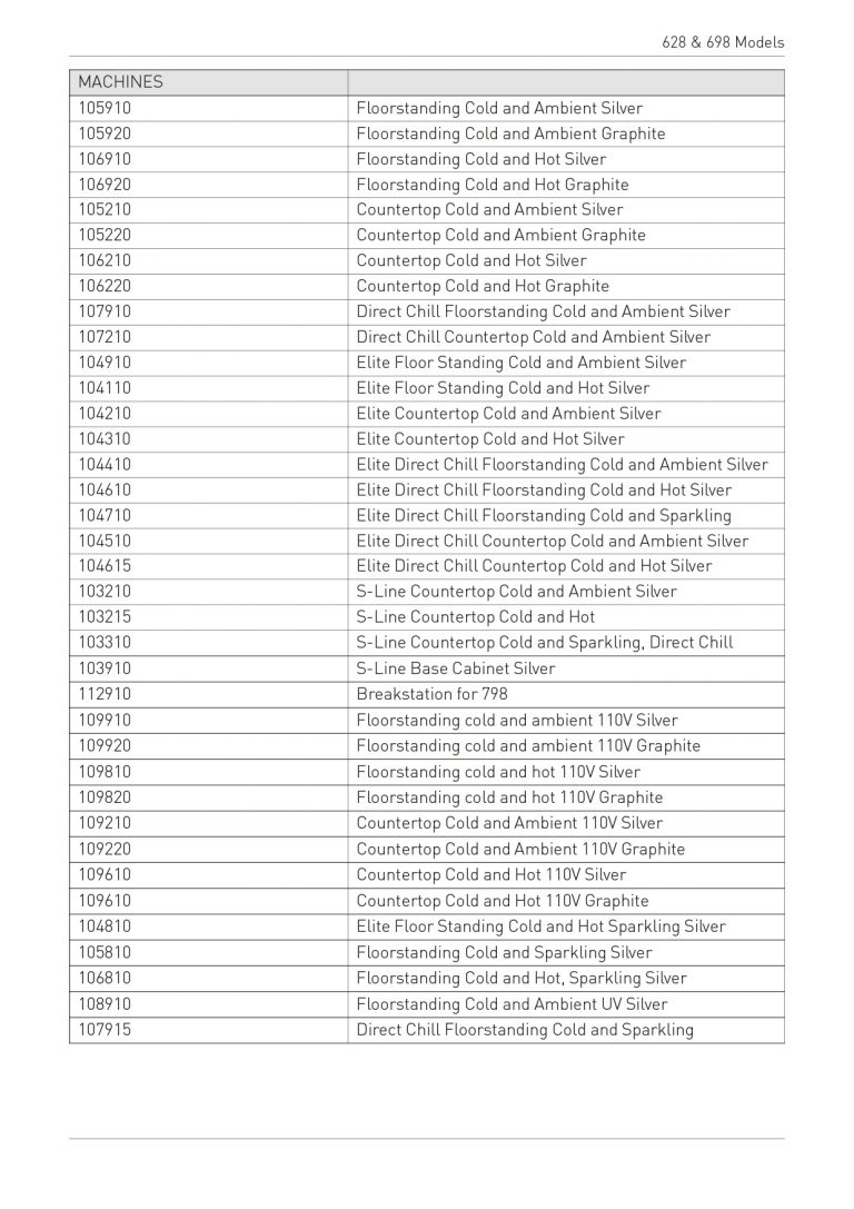
- Parts Listing
- Returns Procedure
- Step-by-step Procedures
Release date 10.04.2015
B2.1 Install & Operation Manual
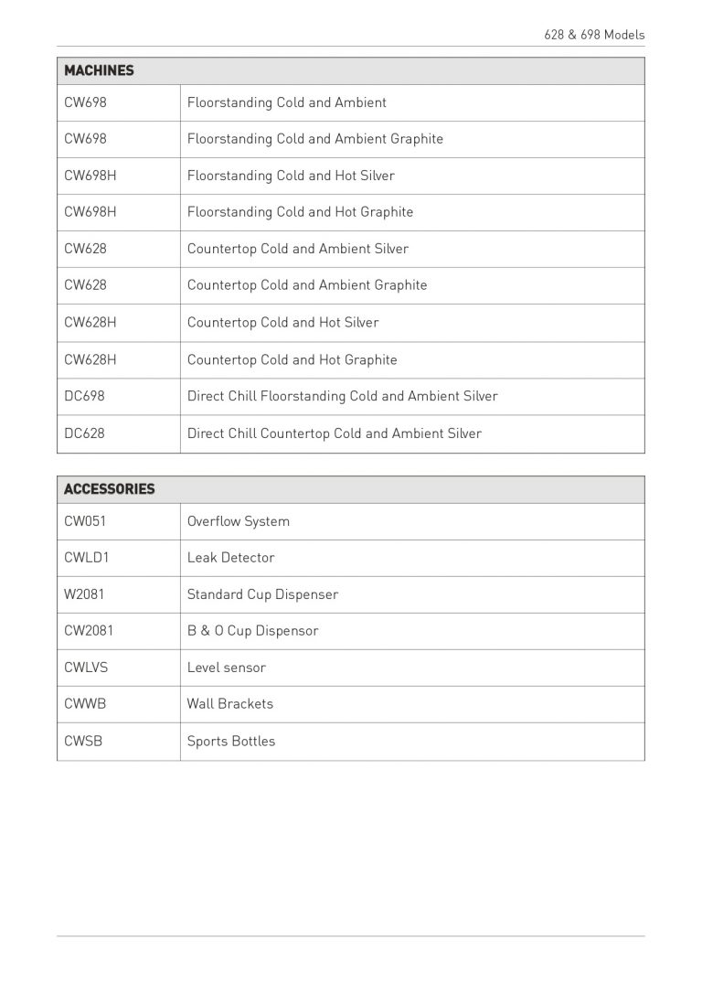
Model Overview
Range Overview
A comprehensive range of watercoolers, available in two different operational types:
• “Classic”- Reservoir Model (Cold Water Storage Tank)
• “Direct Chill” Model (No Stored Drinking Water)
Both types are available as:
• Floorstanding
• Countertop
All Reservoir models are available as either
• Cold and Ambient
• Hot and Cold
Direct Chill models are currently only available as Cold and Ambient.
All types
All b & o “Classic” & “Direct Chill” models are self contained machines with robust steel sided cabinets and attractively moulded front and top panels.
An IEC Power Lead is supplied for connection to the IEC socket found on the rear of all models.
Floorstanding Models
All are supplied with an opening lower door and are prefitted with a removable filter mounting bracket. A water inlet fitting is provided to the bottom right hand corner.
(Adjustable feet will be standard from 2009).
Countertop Models
A void is provided with the front panel area to accommodate most filter types where external installation in an under cabinet is not possible.
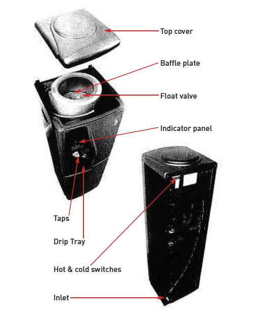
“Classic” Reservoir Model
Water is fed into the reservoir via the Float Valve mounted in the Tank Lid. The Float Valve controls the water level in the tank. Ensure a Pressure Reducing Valve is fitted to all supplies greater than 3.5 bar pressure.
The Baffle Plate inside the Cold Tank maintains separation between the lower chilled water and upper ambient water. (The cooling system only chills water in the lower part of the Cold Tank).
Dispense is at gravity pressure only via push operated Taps.
The Cold Temperature is thermostatically controlled via the adjustment screw on the back of the machine. This is factory set and is not necessary to adjust in most cases. (See Controls)
On Hot & Cold versions, the Hot Tank is fed with ambient temperature water from the upper area of the Cold Tank.
The Hot Temperature is thermostatically controlled with sensors on the outside of the Hot Tank. These are preset and are not adjustable. The system is designed so that the Hot Tank is impossible to run dry under normal usage. Running dry can only occur if the inlet water is drained using the Drainage Point provided. In the event of running dry the Overheat sensor would switch off the heater until manually reset.
Controls
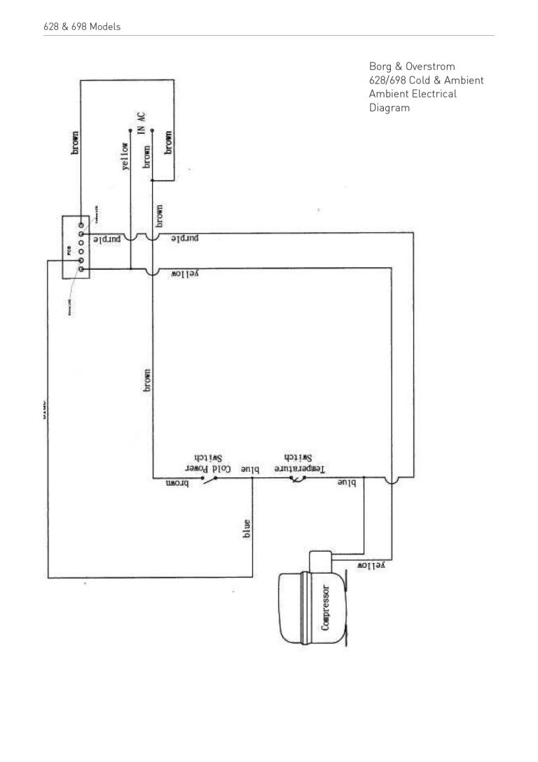
Cold & Ambient Models
Electrical On/Of switch – At upper rear of machine. Switches on Cooling Operation.
Cold Thermostat – At rear of machine. On Classic models and inside the machine, next to the Chill Tank, on DC Models.
Cold Thermostat

NB: Turn clockwise to decrease water temperature
Ambient Tap: Press downwards to dispense Ambient water
Cold Tap: Press downwards to dispense Cold Water
Green LED (Top): Colours to show Cooling Operation is switched on
Yellow LED (Bottom): Colours to show when compressor is operating
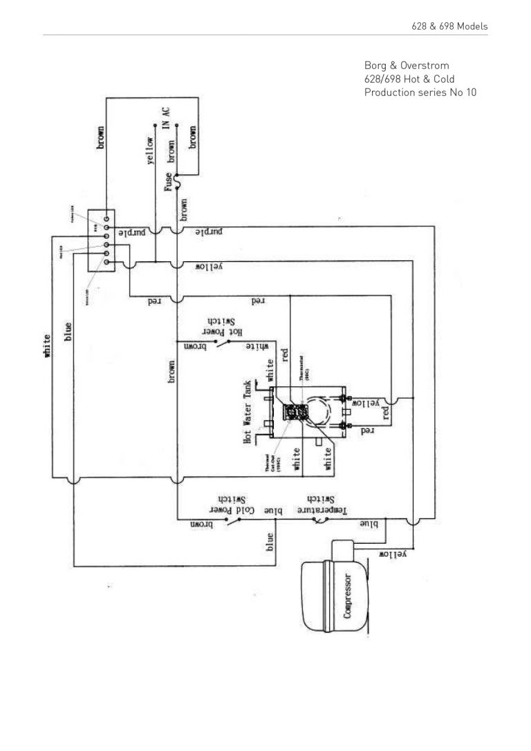
Hot & Cold Machines:
Electrical On/Off Switches:
At upper rear of machine
Cold – Switches on Cooling Operation
Hot – Switches on Heating Operation
10A Fuse: At upper rear of machine
Hot Tap: Lift Safety Tag and press downwards to dispense Hot Water
Cold Tap: Press downwards to dispense Cold Water
Green LED (Top): Colours to show Cooling Operation is switched on
Yellow LED (Middle): Shows when heating mode is switched on
Red LED (Bottom): Colours to show when main heater is operating (i.e. Off when water is at temperature)
Hot Tank Overheat Reset Button: On sensor on side of Hot Tank (Press to operate if required. Ensure electrical power is disconnected before doing so).
Installation & Operation Guide (CW698)
IMPORTANT – the guide must be read before attempting to connect the machine.
Introduction
Congratulations on your wise choice of water cooler. Your Borg & Overström water cooler will provide you with a continuous supply of water 24 hours a day. To ensure that his product will always perform as it truly should, the user should initially read this manual thoroughly and follow all the instructions before operation of the unit commences.
Installation
The water connection to the Borg & Overström water cooler is via a 1/4” supply. The connection can either be made utilising the bulk head connector found at the rear of the machine or by connecting an in-line straight connector direct to the pipe inside the rear of the machine. It is advisable that in any case an in-line isolation tap should be installed on the supply just behind the machine in case of emergency.
Operation Method
1. Having connected the water supply to the rear of the machine, the water supply should be turned on and you will hear the reservoir within the machine start to fill. Once this has stopped filling, the entire tank should then be drained and allowed to refill before operation of the machine commences. If in any doubt at this stage please add some sanitisation fluid to your initial tank of water so as to flush the machine before use. Once the machine has refilled with water the machine can be connected to the mains supply and switched on. The switch at the rear of the machine then needs to be turned on before operation can commence.
NB. If your water cooler has a hot water facility please allow time for the hot tank to fill up before turning on. To draw water into the hot tank, the hot tap must be held open until water starts to dispense.
2. Both LEDs on the display panel should now be showing. After initial chilling operation has been completed the chilling lens will go off, which is the bottom of the two lenses showing.
Machine Positioning
1. It is important that at least 10cm is left between the back of the machine and the surface against which it is placed. This is to ensure that the machine does not in any way overheat.
2. The machine must be kept away from any direct sunlight.
3. It is important that the machine is connected to an RCD connected supply making doubly sure that the voltage supply is compatible with the machine.
Sanitisation & Cleaning
1. Please make sure that the machine has been disconnected from the electrical supply before any cleaning commences.
2. The lid of the machine should be removed exposing the inside of the water tank. Now press both the cold tap and the ambient tap to drain all the water from the reservoir until no water can be seen. Remove the baffle plate found in the centre of the tank passing it around the float valve to remove it completely. At this stage it is possible to see whether any water has been left in the base of the tank. A hundred millilitres of sanitising fluid can now be tipped into the reservoir.
3. The water can be turned on again briefly to half fill the reservoir with sanitising fluid. The upper half of the reservoir should be cleaned utilising sanitisation wipes supplied by Azure. Whilst the sanitisation fluid is having its effect, please clean the external casing with Azure sanitisation wipes. Once the sanitisation fluid has been left for a satisfactory period of time, please flush the water cooler through at least once by turning the water back on. When this has been completed, the machine can be reassembled and your sanitisation is complete. Please now switch the power back on. If you have any question regarding sanitisation please do not hesitate to ring Azure Head Office on 0845 4 50 30 90.
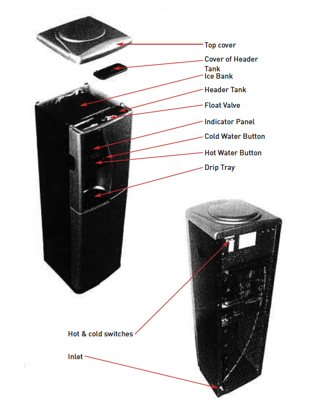
Installation & Operation Guide (DC698)
IMPORTANT – the guide must be read before attempting to connect the machine.
Introduction
Congratulations on your wise choice of water cooler. Your Borg & Overström water cooler will provide you with a continuous supply of water 24 hours a day. To ensure that his product will always perform as it truly should, the user should initially read this manual thoroughly and follow all the instructions before operation of the unit commences.
Installation
The water connection to the Borg & Overström water cooler is via a 1/4” supply. The connection can either be made utilising the bulk head connector found at the rear of the machine or by connecting an in-line straight connector direct to the pipe inside the rear of the machine. It is advisable that in any case an in-line isolation tap should be installed on the supply just behind the machine in case of emergency.
Operation Method
1. Having connected the water supply to the rear of the machine, the water supply should be turned on and you will hear the header tank and ice bank starting to fill. Once this has stopped filling, the machine can be connected to the mains supply and switched on. The switch at the rear of the machine then needs to be turned on before operation can commence.
NB. If your water cooler has a hot water facility please allow time for the hot tank to fill up before turning on. To draw water into the hot tank, the hot tap must be held open until water starts to dispense.
2. Both LEDs on the display panel should now be showing. After initial chilling operation has been completed the chilling lens will go off, which is the bottom of the two lenses showing.
Machine Positioning
1. It is important that at least 10cm is left between the back of the machine and the surface against which it is placed. This is to ensure that the machine does not in any way overheat.
2. The machine must be kept away from any direct sunlight.
3. It is important that the machine is connected to an RCD connected supply making doubly sure that the voltage supply is compatible with the machine.
Sanitisation & Cleaning
1. To commence sanitisation, simply isolate the water supply and remove the filter cartridge.
2. Having removed the filter cartridge you now connect the dosing cartridge supplied by Azure with 125ml of sanitisation fluid inside.
3. Now simply hold on the cold and ambient water button until the sanitisation fluid has been flushed through the system.
4. The last stage is to fully clean the external casing with Azure sanitisation wipes. When this has been completed your sanitisation is complete.
If you have any question regarding sanitisation please do not hesitate to ring Azure Head Office on 0845 4 50 30 90.
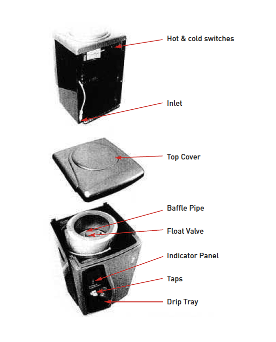
Installation & Operation Guide (CW628)
IMPORTANT – the guide must be read before attempting to connect the machine.
Introduction
Congratulations on your wise choice of water cooler. Your Borg & Overström water cooler will provide you with a continuous supply of water 24 hours a day. To ensure that his product will always perform as it truly should, the user should initially read this manual thoroughly and follow all the instructions before operation of the unit commences.
Installation
The water connection to the Borg & Overström water cooler is via a 1/4” supply. The connection can either be made utilising the bulk head connector found at the rear of the machine or by connecting an in-line straight connector direct to the pipe inside the rear of the machine. It is advisable that in any case an in-line isolation tap should be installed on the supply just behind the machine in case of emergency.
Operation Method
1. Having connected the water supply to the rear of the machine, the water supply should be turned on and you will hear the reservoir within the machine start to fill. Once this has stopped filling, the entire tank should then be drained and allowed to refill before operation of the machine commences. If in any doubt at this stage please add some sanitisation fluid to your initial tank of water so as to flush the machine before use. Once the machine has refilled with water the machine can be connected to the mains supply and switched on.The switch at the rear of the machine then needs to be turned on before operation can commence.
NB. If your water cooler has a hot water facility please allow time for the hot tank to fill up before turning on. To draw water into the hot tank, the hot tap must be held open until water starts to dispense.
2. Both LEDs on the display panel should now be showing. After initial chilling operation has been completed the chilling lens will go off, which is the bottom of the two lenses showing.
Machine Positioning
1. It is important that at least 10cm is left between the back of the machine and the surface against which it is placed. This is to ensure that the machine does not in any way overheat.
2. The machine must be kept away from any direct sunlight.
3. It is important that the machine is connected to an RCD connected supply making doubly sure that the voltage supply is compatible with the machine.
Sanitisation & Cleaning
1. Please make sure that the machine has been disconnected from the electrical supply before any cleaning commences.
2. The lid of the machine should be removed exposing the inside of the water tank. Now press both the cold tap and the ambient tap to drain all the water from the reservoir until no water can be seen. Remove the baffle plate found in the centre of the tank passing it around the float valve to remove it completely. At this stage it is possible to see whether any water has been left in the base of the tank. A hundred millilitres of sanitising fluid can now be tipped into the reservoir.
3. The water can be turned on again briefly to half fill the reservoir with sanitising fluid. The upper half of the reservoir should be cleaned utilising sanitisation wipes supplied by Azure. Whilst the sanitisation fluid is having its effect, please clean the external casing with Azure sanitisation wipes. Once the sanitisation fluid has been left for a satisfactory period of time, please flush the water cooler through at least once by turning the water back on. When this has been completed, the machine can be reassembled and your sanitisation is complete. Please now switch the power back on. If you have any question regarding sanitisation please do not hesitate to ring Azure Head Office on 0845 4 50 30 90.
Cup Dispenser
1. Carefully unpack and inspect for damage.
2. Select fitting position (Normally at top of right hand side panel towards front of machine).
3. Attach self-adhesive pad to mounting bracket and affix to chosen site (Clean area first to ensure good adhesion).
4. Additionally, self tapping screws can also be used to ensure a secure fitting.
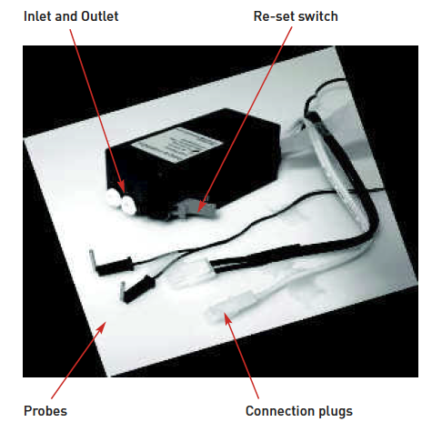
Leak Detector
IMPORTANT – the guide must be read before attempting to connect the machine.
Congratulations, you have chosen wisely to add a Leak Detector to your Borg & Overström water cooler. This product does not in anyway provide a guarantee or insurance against any flooding but provides the means of added prevention. Please ensure that you read this manual thoroughly before proceeding, and take note of the installation and operation procedures to achieve the best results.
Installation & Operation
This product can only be used in conjunction with a Borg & Overström water cooler.
Please follow the step-by-step procedures for installation:
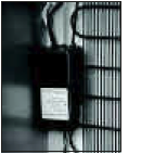
Please fix the Leak Detector as high as possible within the machine. Ensure that the red lever has sufficient space to be activated. It is imperative that the electrical connections are facing upwards and the water pipe is installed into the base of the Leak Controller and that the Leak Controller is mounted vertically.
The detection probes can now be fixed into their locating holes in the channel within the base plate.
The inlet and outlet connection ports for the water are connected via 1/4” push-fit fittings. The pipe already located within the machine must be connected to the outport on the machine and the supply feed coming into the machine must therefore be placed into the inport. Find a connection plug within the back of the machine where the power supply comes in.
Please part the two sections of this connection plug and plug your Leak Controller into these two connections. Note: This will only work one way round (you cannot get it wrong).
Your Leak Detector is now ready for operation. Please ensure that the red lever is in the closed position before plugging in your Borg & Overström water cooler to the mains supply.
Resetting Detector
In the unlikely event of a leak from a Borg & Overström machine the water detector will automatically shut off both the power and incoming water supply. Please follow the following procedures to reset the detector to regain normal operation.
Leaks & Repairs
1. Unplug the machine from the electrical supply. Initially the machine must be left unplugged whilst the repair is being carried out.
2. Identify the cause of the leak and replace any necessary parts. Once this has been carried out thoroughly dry out the channel in the base of the cooler. The probes should then be removed from their locating positions, thoroughly dried and placed back into position.
3. Now push the red lever back into its normal position so as to return to operation. The power can now be switched back on to the cooler and the machine is ready for operation.
4. In the unlikely event that the red lever should trigger once more, then procedures 1 to 3 should be carried out again.
5. Please note that the electrical power to the machine, not just within the machine, must be disconnected for at least 5 seconds to enable the device to reset. A shorter on-off-on cycle time is unlikely to be long enough, and the machine on/off switch will not cut the power to the device.
In the event of any queries please call Technical Support on 0845 4 50 30 90.
Installing the Level Sensor
698/698H Models:

Fig.1
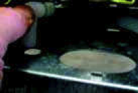
Fig.2

Fig.3
Fig.4
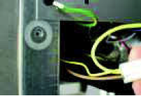
Fig.5
1. Ensure water and electricity supplies to machine are switched off.
2. Remove Tap Cover Panel and disconnect PCB
3. Remove Front Panel. (Be ready to catch Lower Door when lifting Front Panel Clear)
4. Carefully remove screws from rear condenser panel and gently ease panel away.
5. Fit short drainage tube to drainage outlet on rear on Front Panel (with any curve running up in centre as shown in picture 1)
6. Refit Front Panel (and Lower Door) routing drainage tubing under Hot Tank towards back of machine.
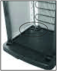
7. Fit Drainage Elbow fitting (see picture 2)
8. Position Elbow through hole in shelf (picture 3) and hold in position by fitting second drainage tube from underside (see picture 4)
9. Position Drainage Tank in lower compartment
10. Fit Control Unit to inside wall of lower compartment with self-adhesive pad as supplied
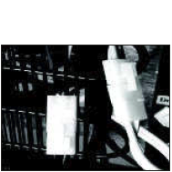
11. Connect small wiring to Float Switch assembly on tank
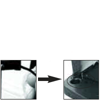
12. Disconnect main wiring terminal block (See picture 5) and insert
Control Unit wiring. (The terminals are individually configured to ensure correct order of connection).
13. Carefully refit the rear condenser panel and turn on the inlet supplies
14. The Level Sensor is now ready for use. The Control unit will bleep when the tank requires emptying after which it will automatically reset.
For further help and advice, please contact:
Azure Technical Support
Tel: ++ (0) 1362 656926
[email protected]
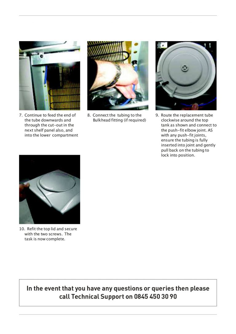
The Waste Kit
Remove Filter Bracket from base of machine and place container inside
Remove top lid. This will allow access to the rear of the drip tray area.
Connect the 2 lengths of silicone tube together using the 90 degree elbow
Connect the shorter length to stem on the rear of the drip tray area.
Feed the tube to the back of the machine where it can be directed into the base.
Connect to the lid of the container.
Remove the bung from the stem of the drip tray and the machine can now be put into service.
Sanitisation Guides
Direct Chill Water Coolers
Turn off incoming mains water, briefly press dispense button(s) to release internal water pressure from the machine and remove filter. If possible temporarily shut off inlet to any hot tank as sanitisation of a hot tank in continuous use is unnecessary.
Add 100 ml of a proprietary sanitisation fluid to a clean and empty service filter cartridge/dosing device and connect into machine. Always ensure to use a reputable branded sanitisation fluid for effective action.
Please note: We recommend using a 3% Hydrogen Peroxide concentration base sanitising fluid of reputable manufacture to the appropriate dilution ratios as supplied with the product or typically 1:30 max. (Stronger concentrations will require larger dilution rates).
Please remember that most sanitisation fluids (including ozone) contain an active caustic/alkaline agent. Always use responsibly and with care remembering that due to its alkaline nature unnecessary concentrated/prolonged contact with any materials, including metals, can cause damage. Always rinse all contact surfaces after use with clean water.
Turn on incoming water, allow service cartridge/doser to fill and then draw off at least 1 litre of water for the machine to ingest the solution. Leave solution for 10 minutes inside machine for sanitisation to take effect. During this time thoroughly clean the machine externally. For this we recommend the use of proprietary disposable sanitisation wipes. Pay particular attention to the dispense faucet and the push button controls. Remember to include the drip tray. If a Waste Overflow System is fitted, this may benefit from flushing through with a small amount of dilute sanitisation fluid. Optionally you may replace the dispense faucet and/or descale it.
After a satisfactory period of time, flush the machine with at least 10 litres of clean water to clear any trace of the sanitisation fluid. Optionally use test strips to check.
Turn off water and remove the service filter/doser and fit a new filter of reputable quality and suited to the site conditions. We recommend pre-flushing the new filter to reduce any risk of any loose media in the filter entering the solenoid valves and possibly causing a malfunction. Retain the service cartridge/doser for reuse.
Turn on incoming water supply and carefully ensure the thorough sanitising of the outside of the machine is completed. Reconnect power and reset any service/filter life monitors accordingly. Ensure any hot tank inlet is reconnected and the tank is purged of air before switching heater on again.
ALWAYS ENSURE ANY RESIDUAL AIR HAS BEEN PURGED FROM BOTH COLD AND HOT SYSTEMS AND ALL IS OPERATIONAL BEFORE LEAVING.
Reservoir Water Coolers
Please make sure that the machine has both been switched off and disconnected from the electrical supply and that the water is turned off, use the taps (and drain point if fitted) to drain off all the water, before any cleaning commences.
The lid of both the machine and the tank should be removed exposing the inside of the water tank. Remove the baffle plate found in the centre of the tank. Any lime scale or mineral deposits should first be removed by manual scrubbing with a non-metallic sponge-scouring pad. For stubborn deposits, most domestic brand stainless steel cleaners can also be used.
If your machine is a Hot & Cold machine please ensure that the inlet to the hot tank is closed off sufficiently to prevent sanitisation fluid entering the hot system.
If using a service dosing cartridge, please now go straight to no 4. At this stage it is possible to see whether any water has been left in the base of the tank, 100ml of sanitising fluid can now be tipped into the reservoir. (We recommend a hydrogen peroxide base sanitising fluid of reputable manufacture using the dilution ratios as supplied with the product.)
Remove the existing filter and install a filter head to suit the service cartridge if necessary. Empty 100ml of sanitisation fluid into the service cartridge and connect the cartridge to the filter head.
The water can be turned on again briefly to half fill the reservoir, forming a sanitising solution. The upper half of the reservoir should be cleaned with sanitisation wipes. Leave for 10 minutes to effect sanitisation, whilst the sanitisation solution is having its effect, please fully clean the external casing with sanitisation wipes, ensuring particular attention is paid to the faucets. Once the sanitisation fluid has been left for a satisfactory period of time please flush the water cooler through at least once with clean water.
When this has been completed, the machine can be reassembled and your sanitisation is complete. Always remember to replace the filter(s) with the appropriate type(s). (Retain service/dosing cartridges for reuse.) Please now switch the power back on.
Ozonation is another alternative, but not a recommended method, as we believe the opportunity should always be taken to inspect the machine internally, remove any scale or mineral build-ups and take interventive action where appropriate.
ALWAYS PURGE AIR FROM THE COLD AND HOT SYSTEM BEFORE SWITCHING POWER ON AGAIN.
Descaling Guides
Reservoir Model
Scale deposits will occur whenever water is heated. Higher deposits will occur with harder water and higher temperatures. Although scale deposits can be reduced through using softened water this is not necessarily desirable due to the adverse effect on taste. Therefore, it is important that descaling is carried out regularly to maintain the high efficiency of operation of your appliance.
The frequency of descaling depends on the hardness of the water and the intensity of usage in each case. At least every 12 months is highly recommended. Although it is primarily the Hot Tank (Water Heater) that requires descaling, it is also necessary to sometimes carry out some in the cold tank.
Please note: Descaling is to remove the inevitable build up of limescale and should not be confused with sanitisation, which is a different procedure for maintaining the necessary hygiene standards for drinking water.
1. Switch off the power and water supply. Drain off water, including Hot Tank. It may be beneficial at this stage to flush through the hot tank with clean water to remove as much loose scale as possible if the tank appears particularly scaled up.
2. Carefully fill a suitable pouring jug with approx 2 ó litres of hot water and add the correct amount of descaler relevant to the enclosed instructions for safe and effective use.
3. Remove the Top Cover from the appliance (and the lid covering the cold tank on later models). Carefully remove the Float Valve and Baffle Plate from the Cold Tank.
4. Slowly pour the descaling solution into the Cold Tank. This will drain directly into the Hot Tank. Continue to add the solution until it also just begins to fill the Cold Tank too. Leave the solution to react with the limescale as directed.
5. Should limescale be present in Cold Tank, carefully treat the areas concerned using the same solution. Also, treat any removed parts such as the Float Valve, after checking the directions for use for compatibility. Similarly, if the outlet taps need treatment, dispense a little solution to draw it into the taps. Examine the small black rubber water stop seal on the Float Valve for any damage or wear and replace if necessary. DO NOT ROTATE
THE SEAL IF IT IS NOT BEING REPLACED AS THIS COULD AFFECT ITS WATER SEAL SEATING AND ALLOW SEEPAGE.
6. After an appropriate time, carefully scrub any surface scale to remove it taking care not to damage the part. If scrubbing of the inside of the taps is required, remove the Front Panel of the appliance and carefully dismantle the taps by unscrewing the ring under the lever and then drawing the lever mechanism upwards out of the body.
N.B. Before removing the taps, drain off any remaining solution in the cold tank.
7. Reassemble any removed parts as necessary and flush appliance through thoroughly with mains water as directed (Carry out sanitisation procedure at this point if desired).
8. Finally, allow appliance to refill, check for any leaks and switch on power supply.
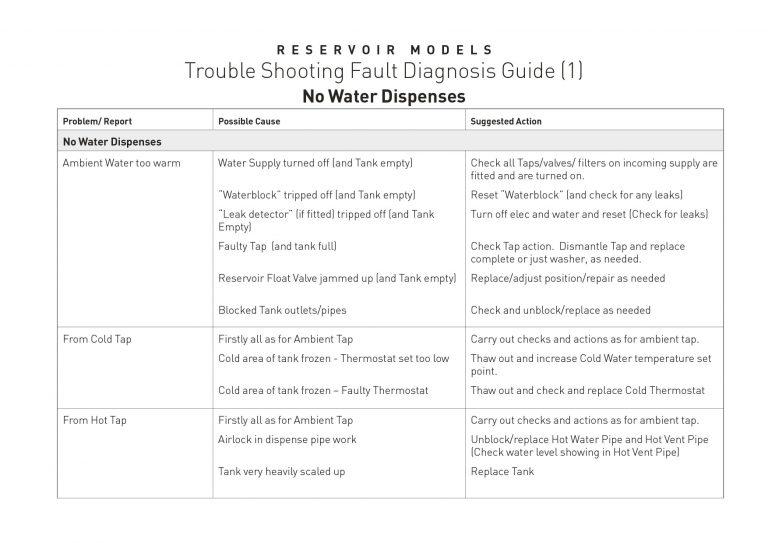
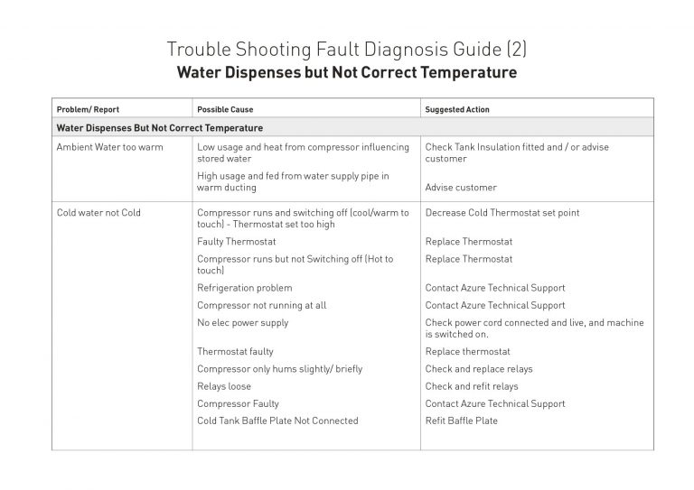
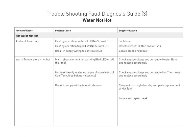
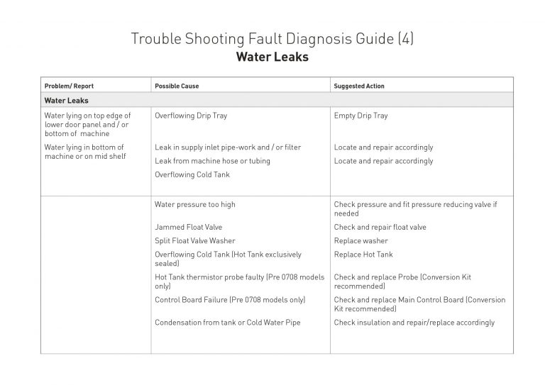
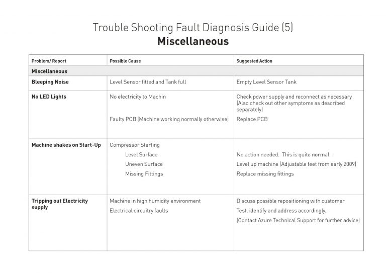
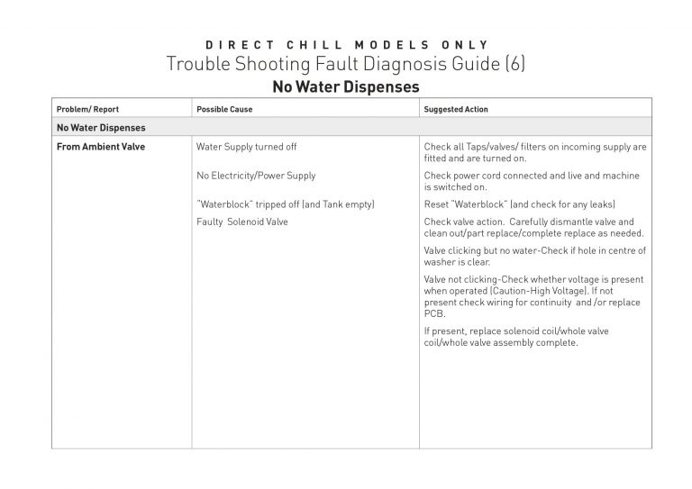
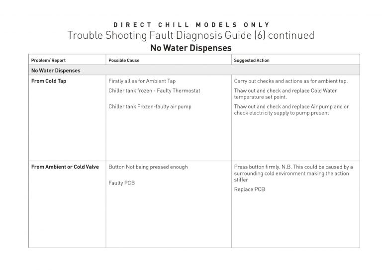
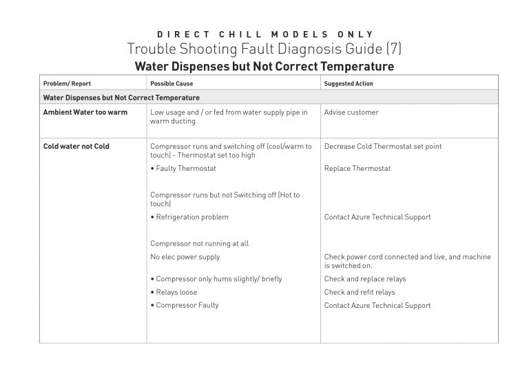
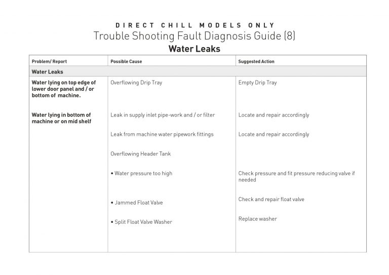
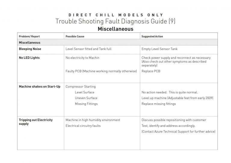
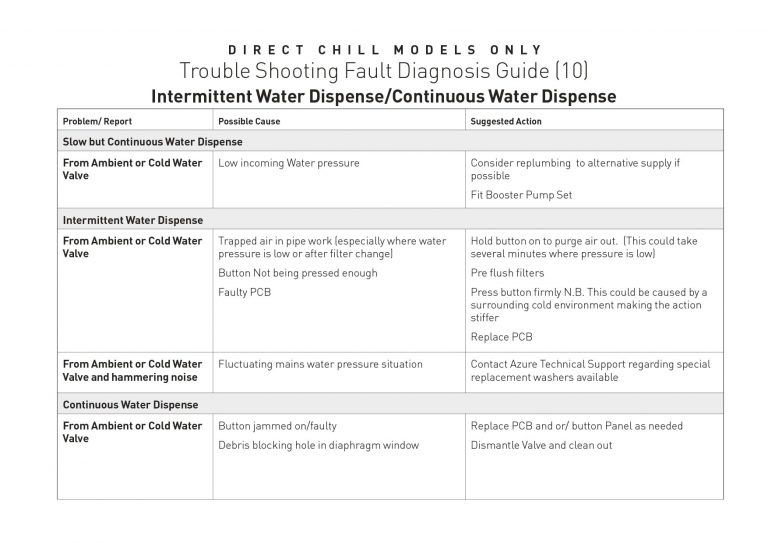
Trouble Shooting Guides
Trouble Shooting Fault Diagnosis Guide
Returns Procedure
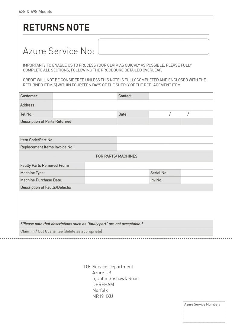
Azure Returns Procedure
If you want to return any of your items please follow the instructions below
• An Azure Service Number must be obtained prior to returning any goods by calling Azure Service on: 0845 450 30 90.
• You will need to provide a full fault description or reason for return for any product being returned.
• The Azure Service Number MUST BE CLEARLY MARKED on the outer transit packaging of your return.
• Please use the tear-off slip overleaf and enter the Azure service number (on the top and bottom of the form where indicated) and attach securely to your packaging.
• Please enclose a copy of your invoices.
• Make sure the item(s) are adequately protected to prevent any damage. Azure cannot be held responsible for any damage to goods returned without adequate protective packaging.
• Please retain the courier collection receipt for your records.
• If you have any further questions or queries relating to the returns Procedure please call Azure service on the above telephone number.
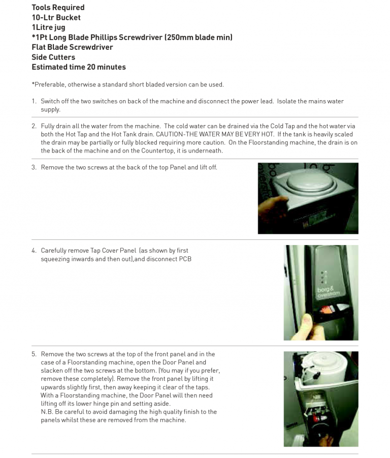
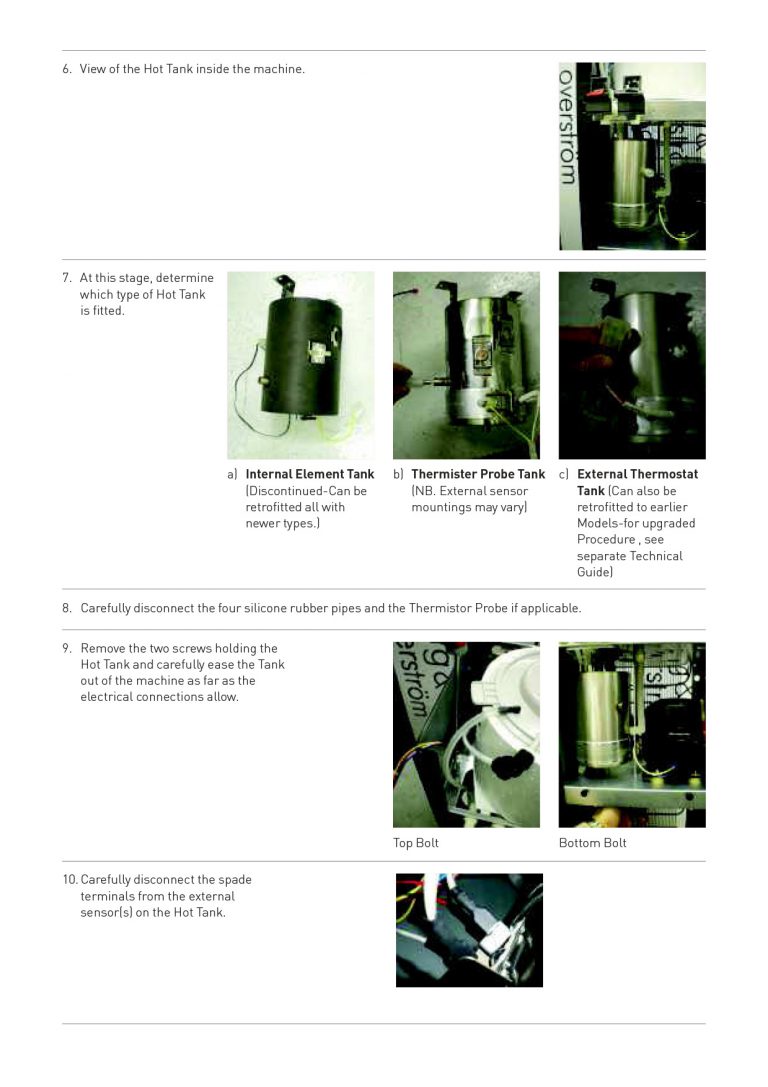
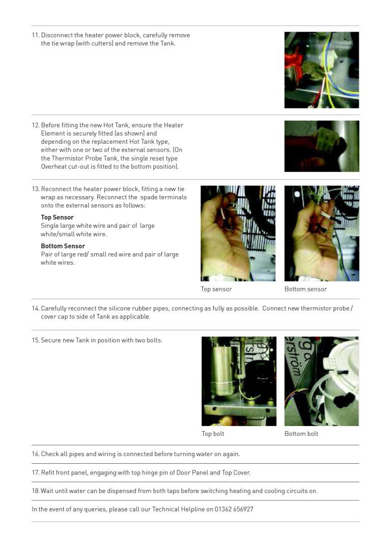
Step-by-step Procedures
Hot Tank Replacement Procedure
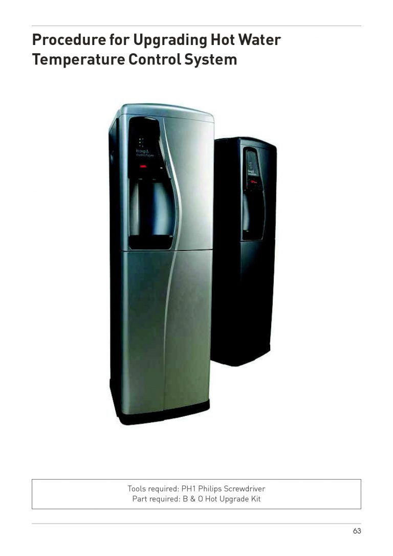
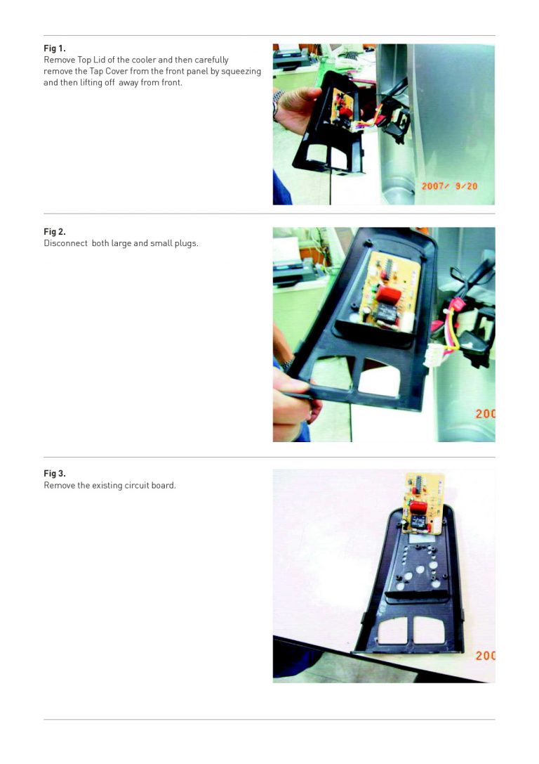
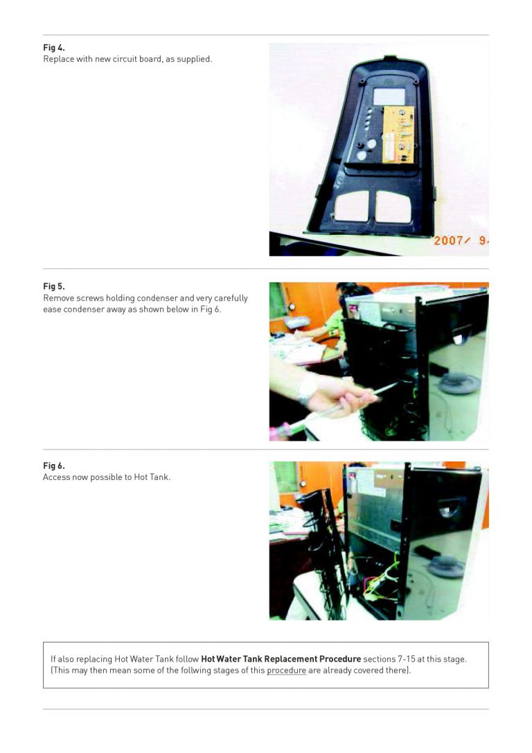
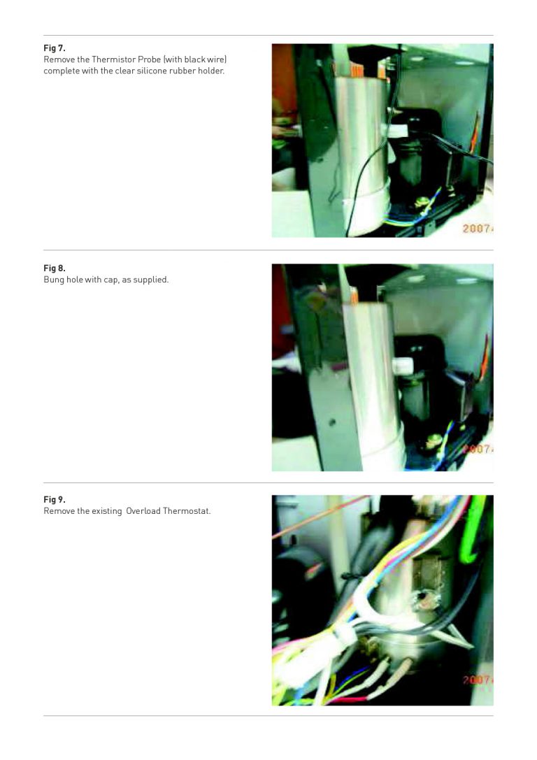
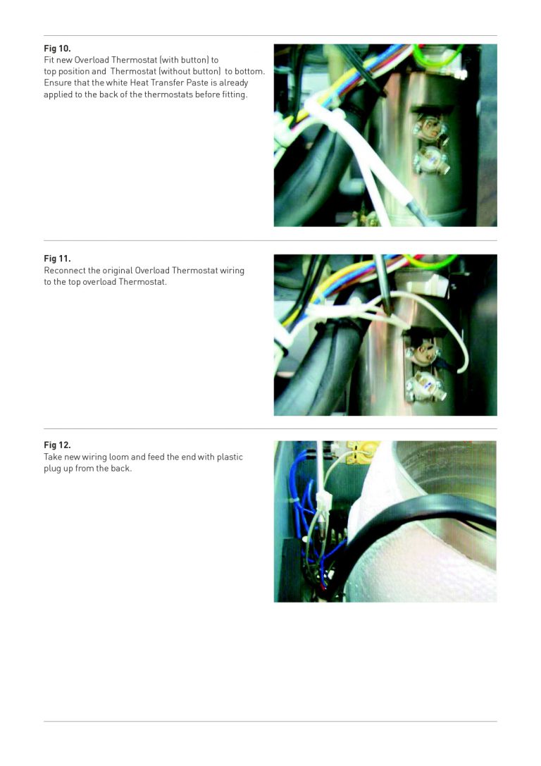
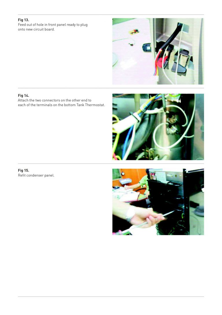
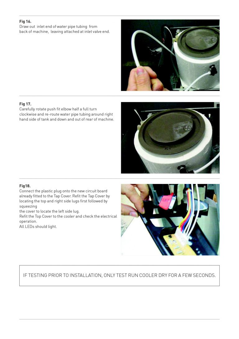
Procedure for Upgrading Hot Water Temperature Control System
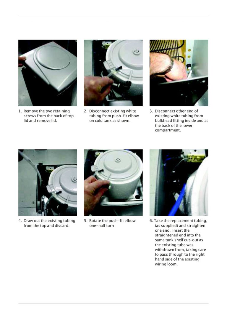
Water Tubing Replacement - Step-by-Step Guide
Azure Technical Advice
Procedure For Checking the Compressor/ Cooling Operation
If the Compressor does not run:
1. Check the LED display
For Cold & Ambient models the green (top) LED should always be on and the Yellow (Bottom) when cooling is called for. If the green is off then check the machines main power supply and the on/off switch.
For the Hot & Cold models the green (top) LED should always be on. If off, check the machines main power supply and the COLD on/off switch.
2. Switching on the Compressor measure the current draw. No operation, but a high draw indicates a jammed compressor (contact Azure Technical Support).
3. The wiring loom can be traced and the live supply check periodically moving towards the compressor (if there is a break at the Cold Thermostat turn the screw clockwise and check whether this closes the circuit. If this doesn’t even when at max, the thermostat should be replaced. Alternatively, for testing purposes only, the thermostat could be bridged).
4. Remove the compressor relay cover and carefully remove the relays. If the power has been even recently connected to the compressor, the solid stat relay will be energised and will need discharging.
5. Check the Compressor resistance readings.
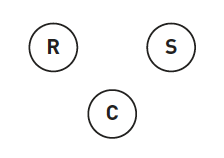
Approx readings could be:
R-C 12ohms
S-C 34ohms
R-S 46 Ohms (sum of both)
N.B. There should always be some variation between compressors. What should be identified is large discrepancies/unbalanced readings.
Also, especially in the case of large discrepancies/unbalanced readings, check for continuity between any of the terminals and the compressor casing. A current will indicate a shorted winding (Contact Azure Technical
support).
6. Checking the relays: Caution: Ensure the larger relay is discharged if recently energised. (This can be discharged by 2MR, 2W resister in the circuit).
Clearly, the best and surest way to test the relays is to replace them one by one and check the compressor operation. Otherwise, each relay component can be basically tested using a meter The Solid State Relay should read approx: 3-6 closed circuit / 3 36 (Ohms) / The Klichson (overload) should read approx 1.7 (Ohms)
7. Ensure the terminals are clean and good contact is made.
If the Compressor Does Run
(Presuming that the Cold water is not being cooled sufficiently)
1. Check the small pipe on the ‘high’ side of the compressor. This should be quite warm after several minutes of normal operation.
2. Following it to the condenser, check the condenser temperature. Normally the beginning will be warmer, cooling off towards the end.
• No or very low temperature could indicate a low refrigerant charge. A low current draw would indicate this. (Contact Azure Technical Support).
• An overly high temperature could indicate a blockage; A high current draw would confirm this. (Contact Azure Technical Support).
3. Continue to follow the pipe work from the end of the condenser to the dryer.
• A frozen / iced dryer will indicate a blockage (Contact Azure Technical Support) Again; a high current draw would confirm this.
4. The dryer exits into the capillary tube. Check this for restrictions and NB: This has a very small bore.
5. The Capillary enters the evaporator. This can be checked visually for any obvious signs of deterioration.
6. The evaporator connects back to the ‘low’ side of the Compressor via the suction pipes. Check this for excessive icing.
Excessive icing could indicate a refrigerant overcharge (Contact Azure Technical Support).
Solenoid Valve Replacement
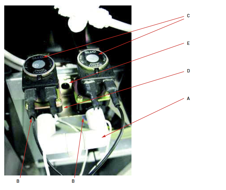
1. Turn off the water supply, press dispense buttons to release water pressure and disconnect electrical power lead.
2. Carefully remove Top Cover, Keypad Panel and Front Panel from machine
3. Pull off Faucet (A).
4. Remove Screw (B) from underside of Mounting Plate (D) securing Solenoid Valve (C) (down to Mounting Plate).
5. Remove Screw (E) securing Mounting Plate (D).
6. Using a suitable flat bladed screwdriver, depress collet ring on push-fit connection on inlet side of solenoid valve (at F) and disconnect pipe work.
7. Remove Solenoid Valve by drawing forwards and away from machine frame.
8. Refit Solenoid Valve by reversal of the above procedure. Ensure correct connection of water inlet pipe work and electrical terminals.
9. Upon completion, check correct operation and for any leaks.